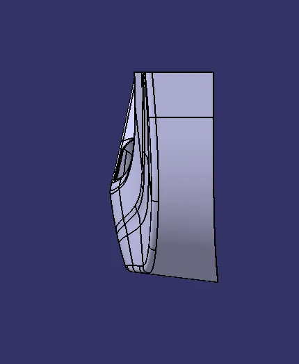
Week 10 - Challenge 3 - Door Trim Lower with Engineering Features
DOOR TRIM LOWER WITH ENGINEERING FEATURES
AIM
To create Solid Body from the given Class A surface and create Heat stakes and Locators on it.
INTRODUCTION
Heat stakes are small protrusions on a plastic part that are melted and reshaped to join another component, usually metal or plastic. This process, called heat staking, creates a strong, permanent bond without the need for adhesives or fasteners. It is commonly used in automotive, electronics and medical device manufacturing to assemble components securely while maintaining a clean and precise finish.
4-way and 2-way locators are used in fixture design position and restrain a workpiece accurately. A 4-way locator restricts movement in both the X and Y directions, ensuring precise positioning from all sides. A 2-way locator limits movement in only one direction, allowing controlled adjustment in other.
PROCEDURE
Steps of the challenge
1. Create a tooling axis for Draft Analysis
2. Perform Draft Analysis on Class A surface
3. Create Class B surface
4. Create Class C Surface
5. Create a Solid Part
6. Model Locators and Heat stakes on the Solid Part
7. Perform Draft Analysis on the Final Part
1. Create a tooling axis for Draft Analysis
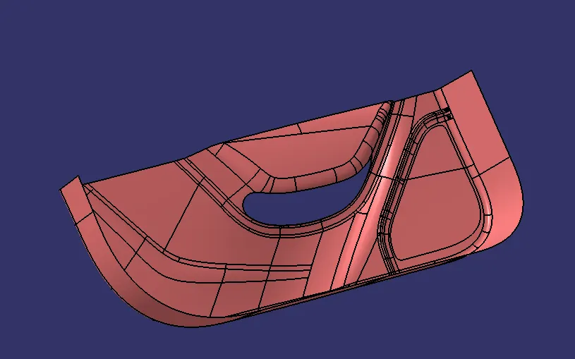
The given Class A surface is shown below.
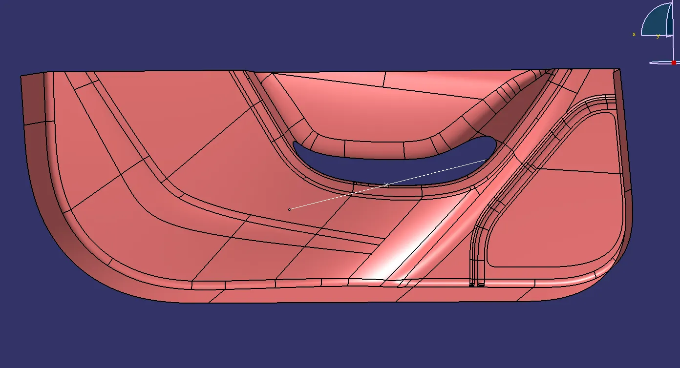
To create the tooling axis we find the direction - X, Y or Z - from which all the surfaces are visible. It is found that almost all surfaces are visible from the Y direction. A point is created on a surface followed by the Tooling axis passing through it. The tooling axis is as shown below.
2. Perform Draft Analysis on Class A surface
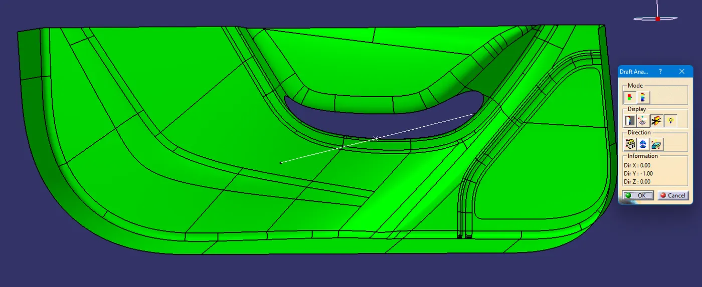
Draft Analysis is performed on the Class A Surface and the results are obtained as shown in the image below.
3. Create Class B surface
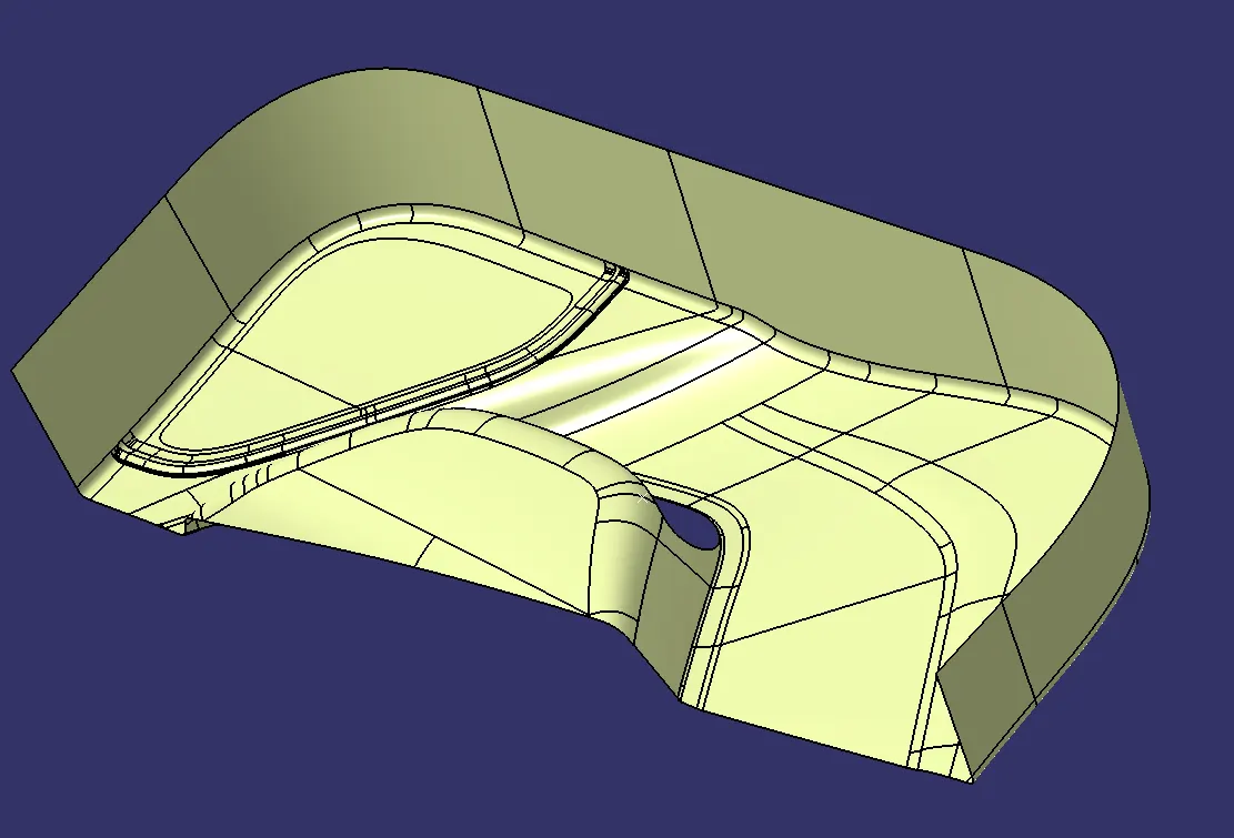
Class B Surface is created by offsetting the Class A surface inwards to a distance of 2.5mm which will be the thickness of the solid part. While offsetting the Class A surface, the resulting surface is obtained with some gaps or patches. The patches are as shown below.
i. 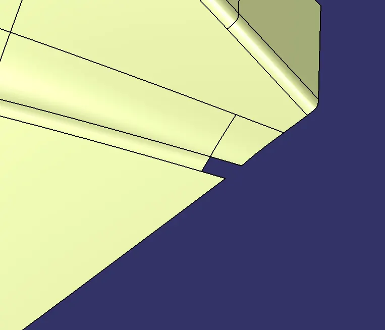
ii. 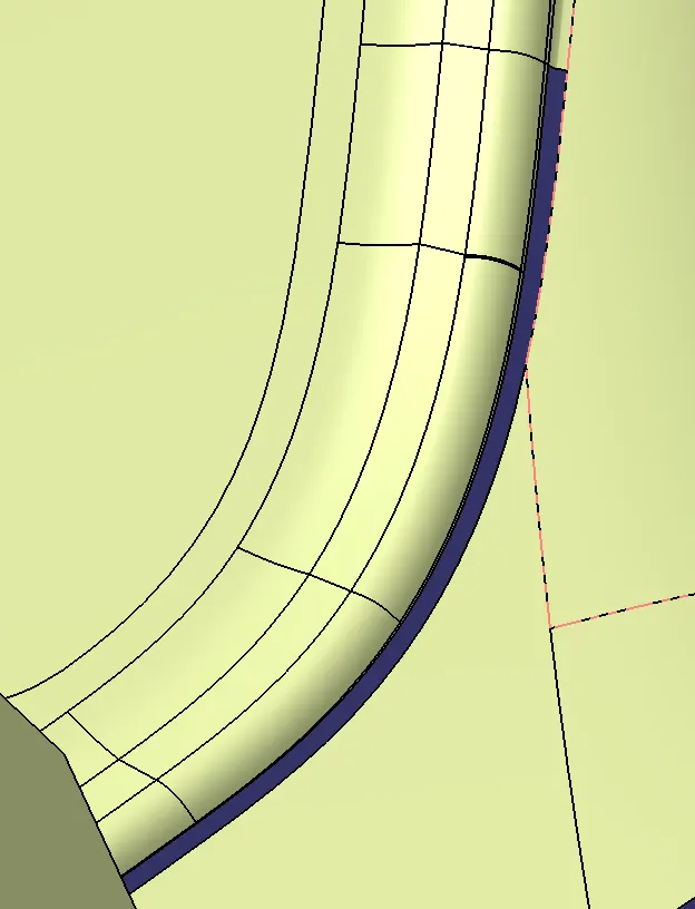
iii. 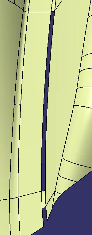
iv. 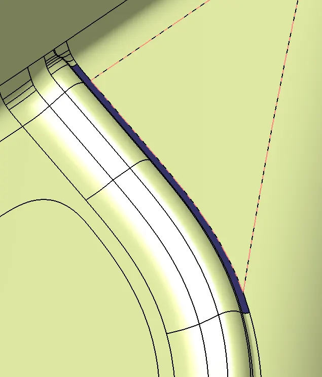
These patches are solved by using Multi-section surface command. The solved Class B surface is obtained as shown below.
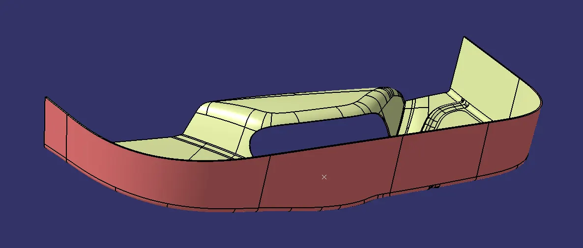
Class A and Class B surface together is as shown below.
4. Create Class C Surface
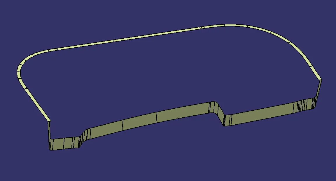
Class C surface is the surface that connects both Class A and B together. It is obtained by sweeping the boundary - which is split into two - of Class A. Class C surface is obtained as shown below.
5. Create a Solid Part
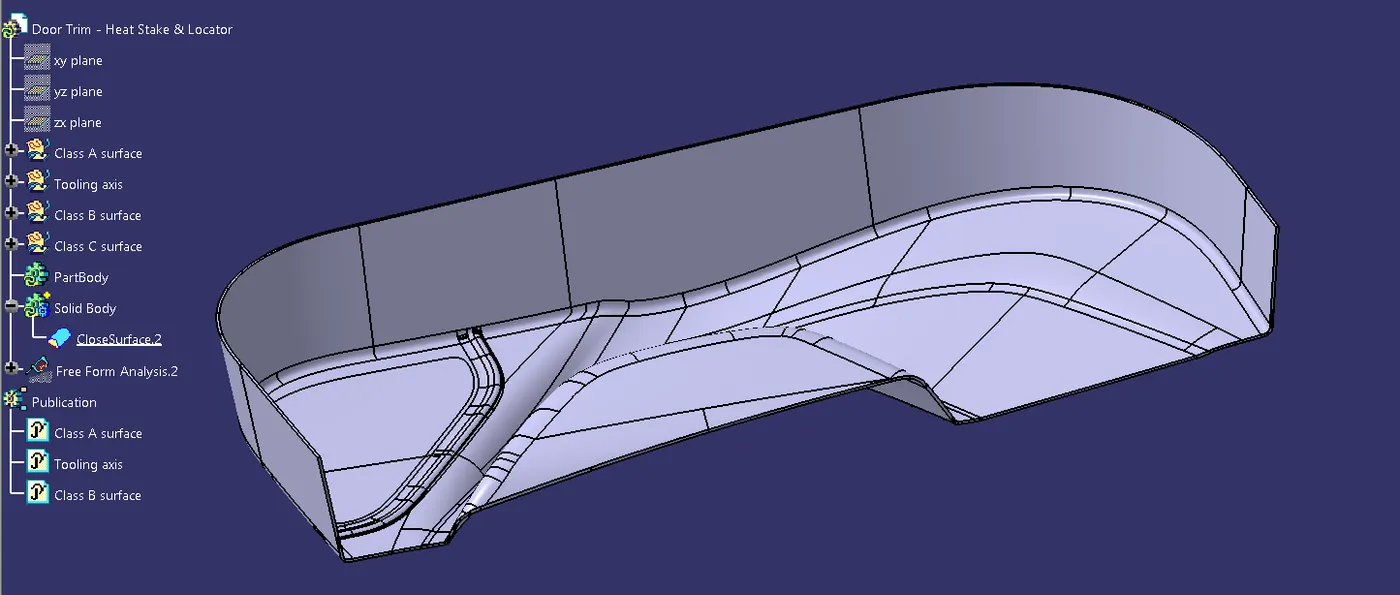
After the creation of Class C surface, we join it with the Class A surface and Trim it with Class B to obtain the final surface.
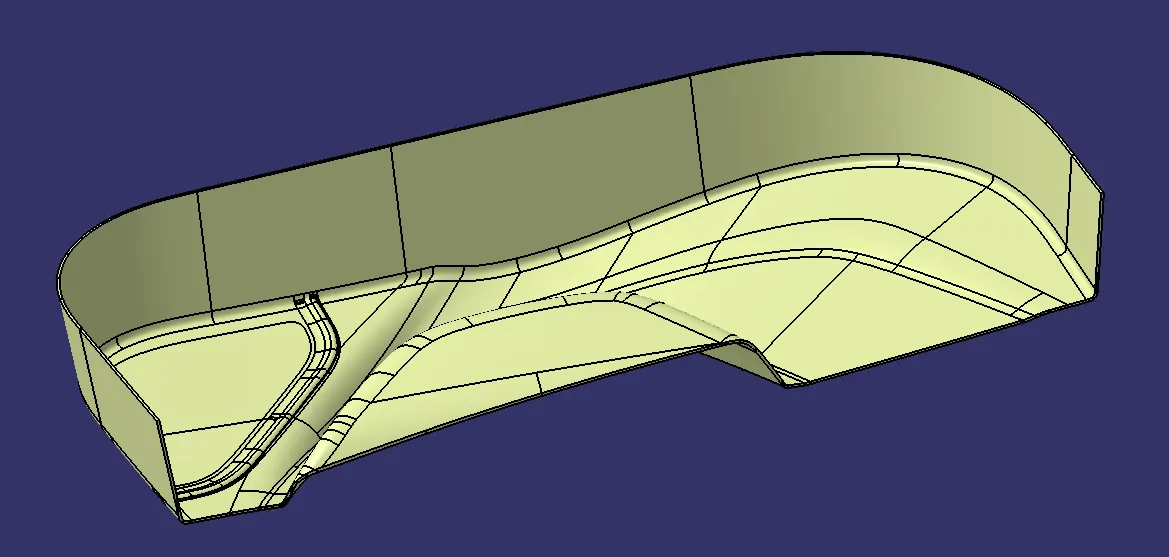
This surface is made into a solid part by using the Closed Surface command in the Part Design Workbench.
6. Model Locators and Heat stakes on the Solid Part
i. Creating 4-way Locator
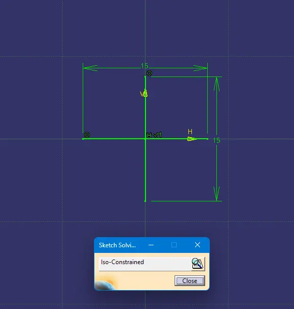
The above image shows the dimension/sketch of the 4 way locator. This sketch is extruded 20mm using the Pad command where it is given a thickness of 1mm. The extruded part is drafted to an angle of 0.5 degrees. It is given a Chamfer of 3mm 45degrees and Fillets as shown in the image below.

ii. Creating 2-way locator
The sketch for the 2-way locator is as shown below.
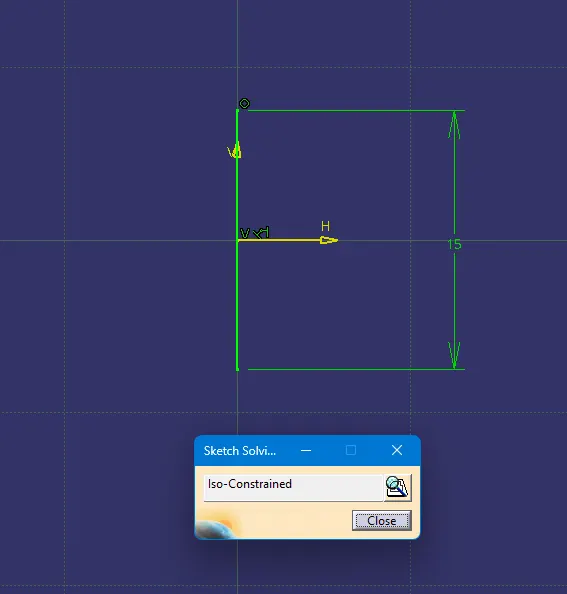
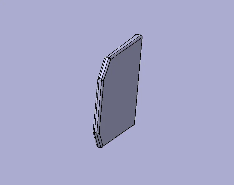
Similar to the 4-way locator, the 2-way locator is extruded, thickened, chamfered, and filleted using similar dimensions. The resulting part is as shown below.
iii. Creation of Heat stakes and ribs
The Heat stakes are created by using the sketch shown below.
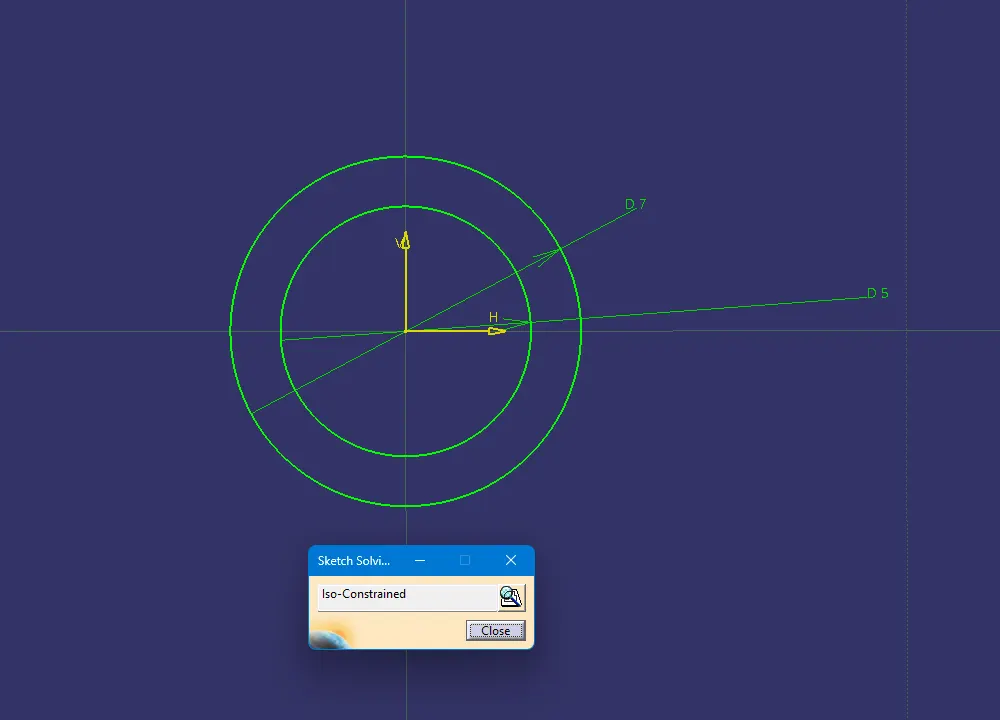
It is then extruded to 20mm and filleted around the edges for 0.3mm.
For creating the ribs we create the following sketch.
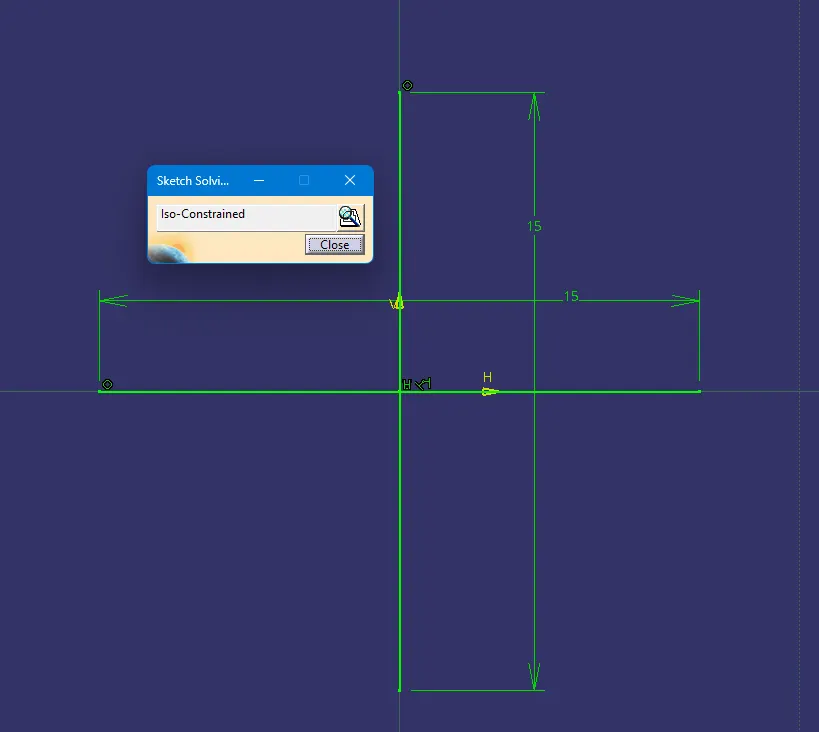
This sketch is extruded to 10mm, thickened and filleted. This extruded rib is the union trimmed with the heat stake and the following part is obtained.
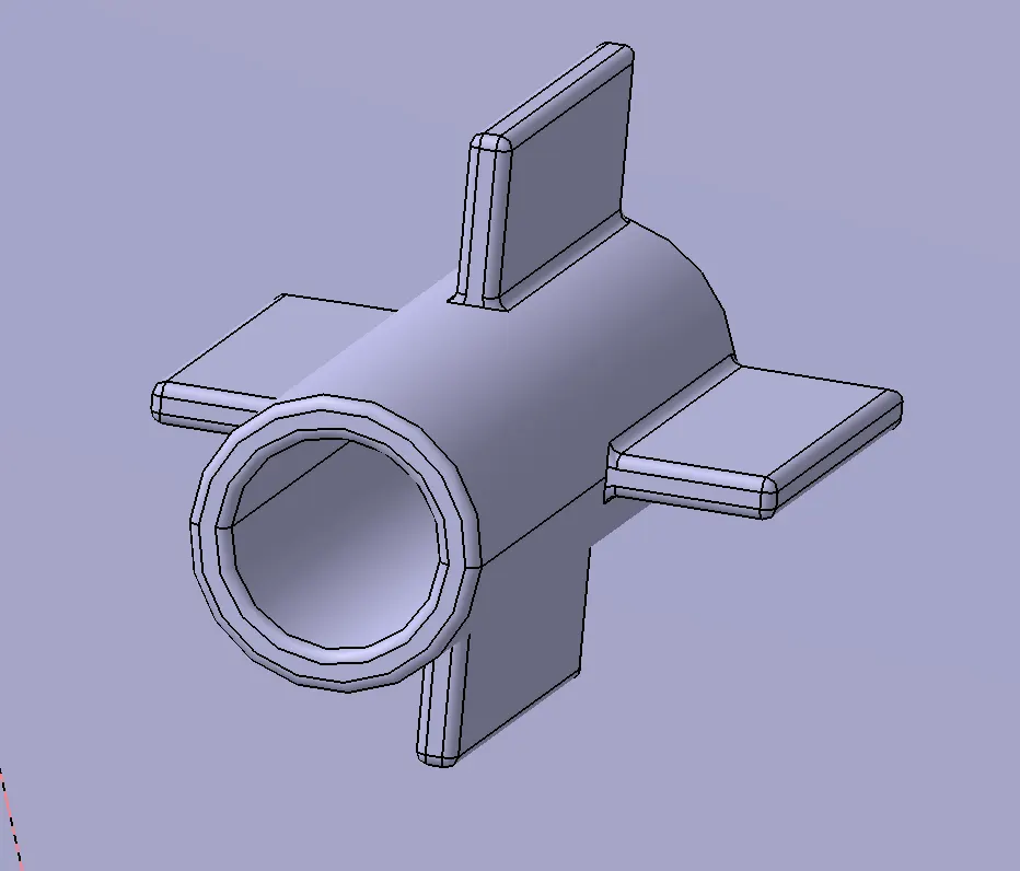
The locations of the multiple heat stakes are as shown below.
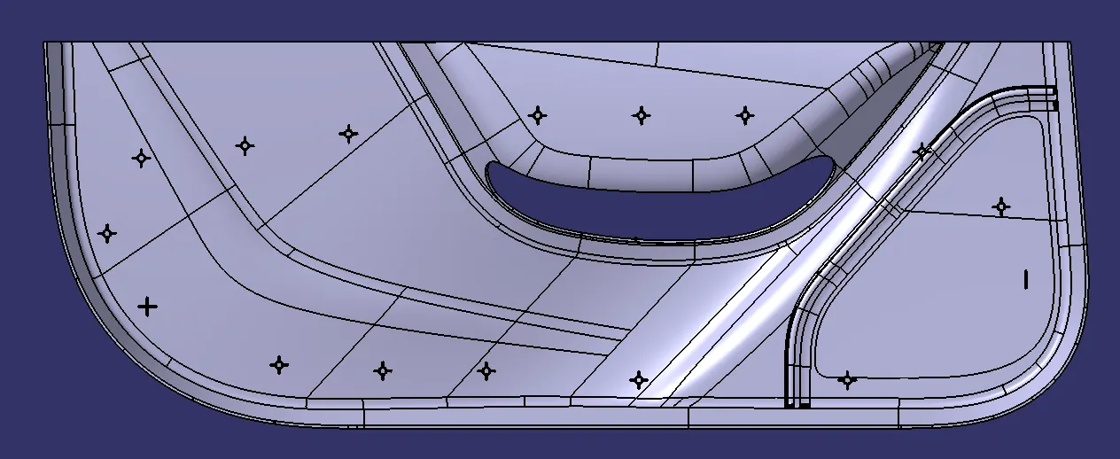
After creation of all the heat stakes we obtain the final part.
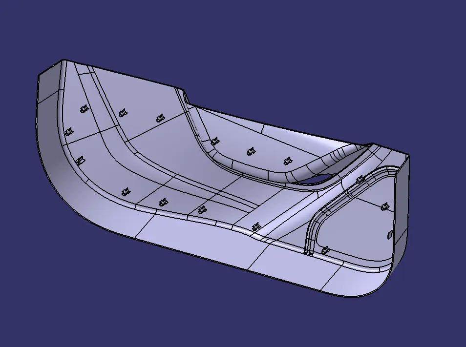
7. Perform Draft Analysis on the Final Part
Draft analysis is performed on the final part and the result is obtained.
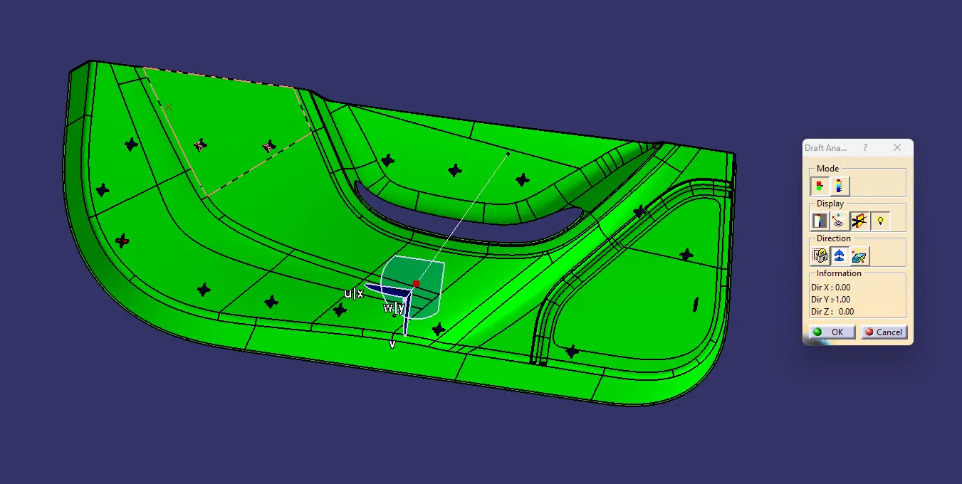
CONCLUSION
A Solid part is created from the provided Class A surface and the creation of Heat Stakes and Locators were successfully done.
ADDITIONAL IMAGES
1. Design Tree
The Geometrical Sets are as shown below.
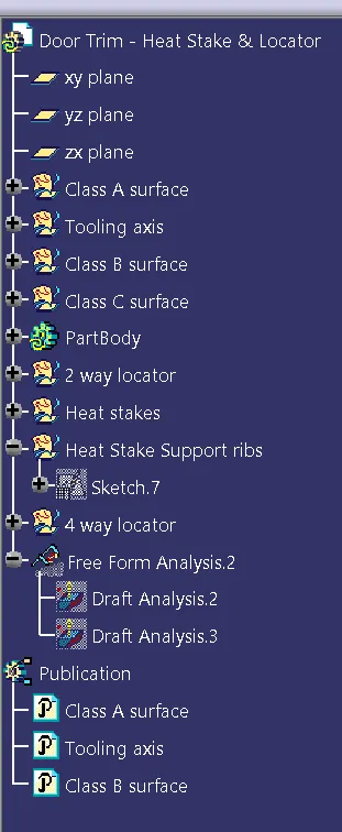
The part design tree is shown below. 1 -13 indicated the heat stakes.

2. Isometric View
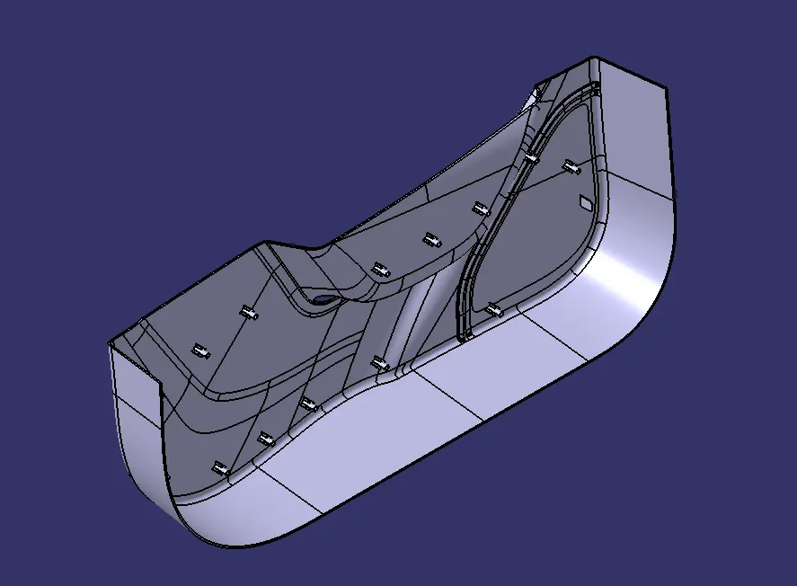
3. Top View
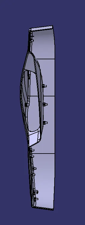
4. Front View
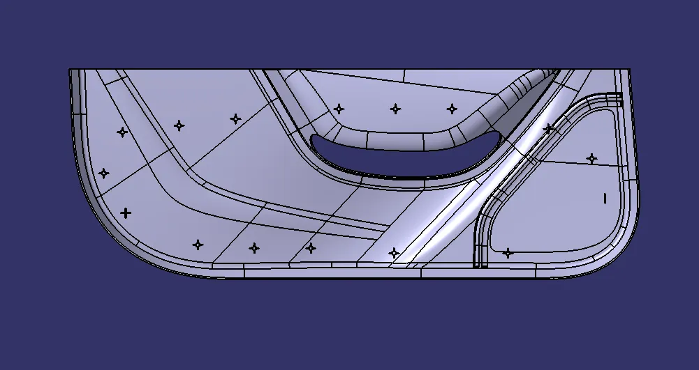
5. Side View