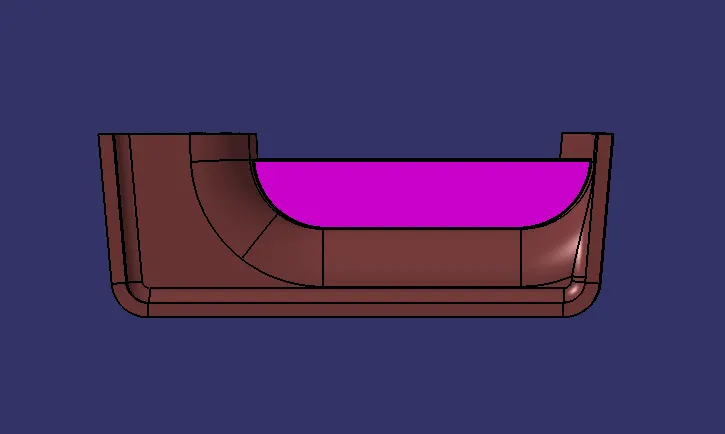
Week 10 - Challenge 1- Attachment Feature Creation (Ribs & Screw Boss)
ATTACHMENT FEATURE CREATION (RIBS & SCREW BOSS)
AIM
To design effective attachment features, including Ribs and Screw Bosses, by creating a Solid model from the given Class A Surface.
INTRODUCTION
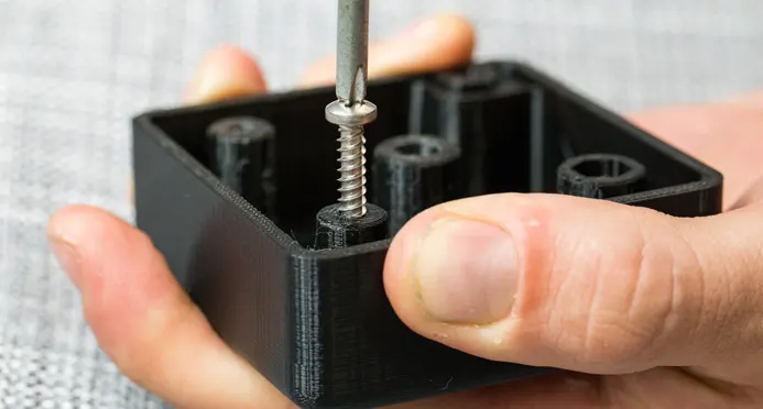
A Screw Boss is a cylindrical feature designed to accommodate screws or other fasteners, commonly used in plastic components for assembly purposes. It provides a secure anchoring point, ensuring strong connections between parts.
PROCEDURE
1. TOOLING AXIS CREATION
We are provided a Class A surface to begin with.
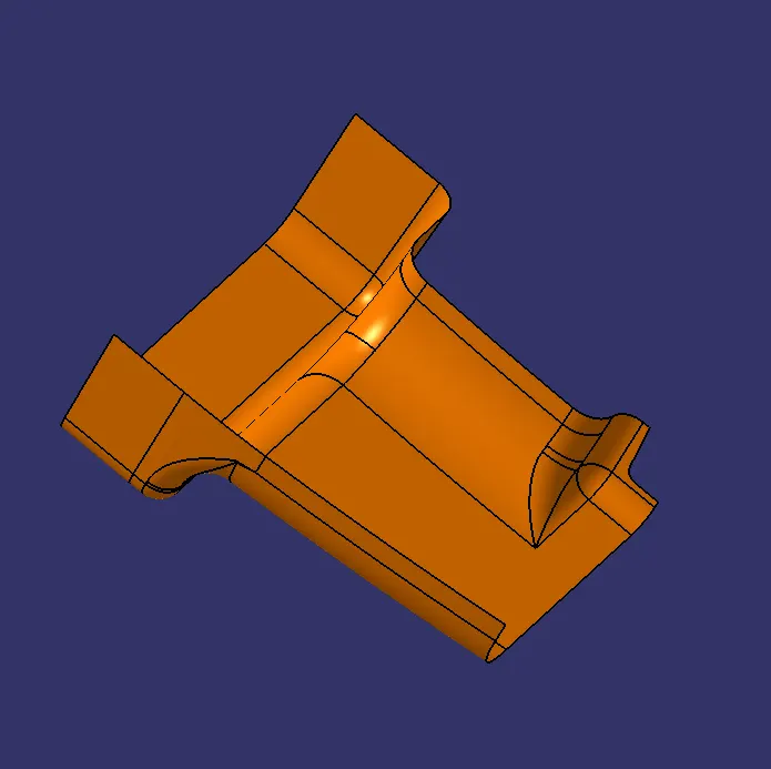
From the given Class A surface we create a Tooling Axis to perform Draft Analysis. The Tooling axis is created by creating a point on an extracted surface as shown below.
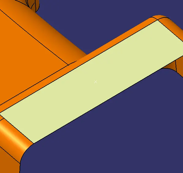
By the Intersection command and creating a bisecting line, we get our tooling axis.
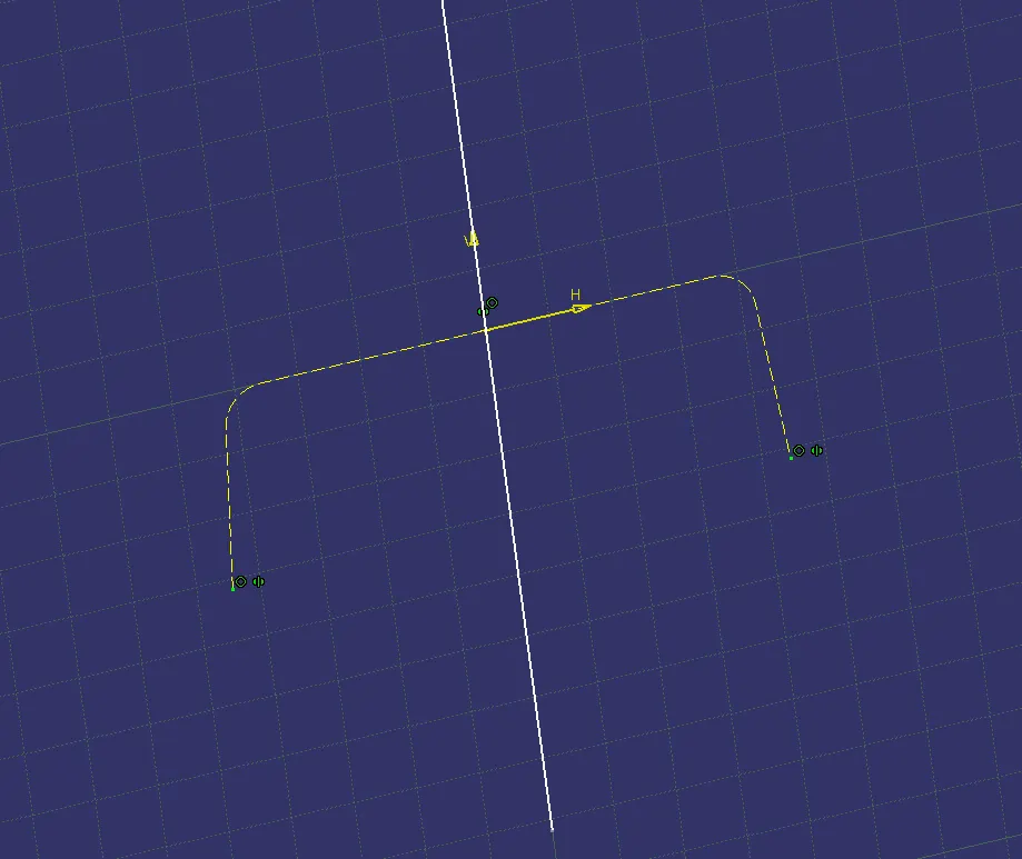
The image above shows the tooling axis is formed by the bisecting method.
The tooling axis on the surface will look like as shown below.
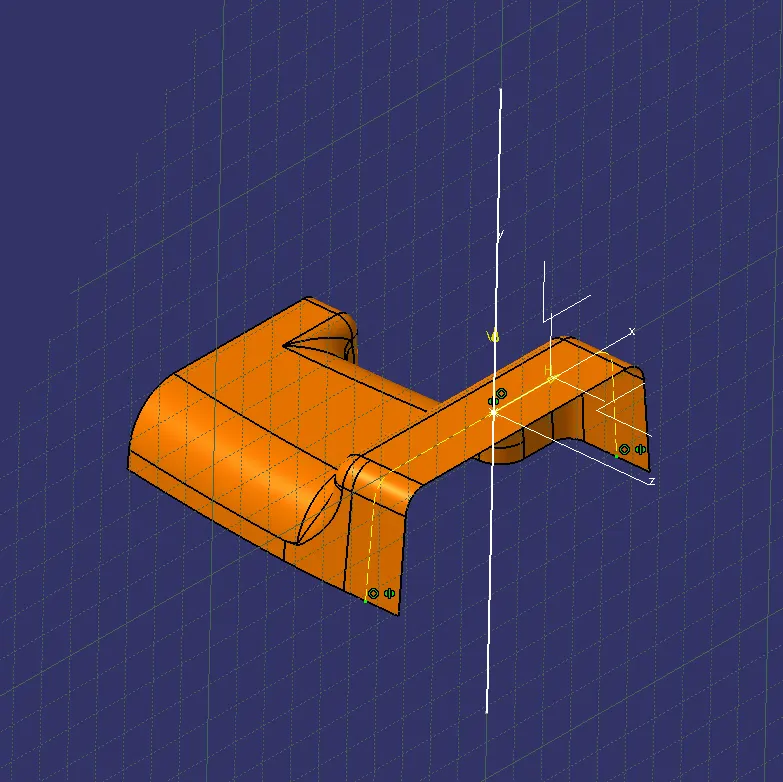
2. DRAFT ANALYSIS ON CLASS A
By using the Tooling axis that was created, we perform draft analysis on the Class A surface and we obtain the following result.
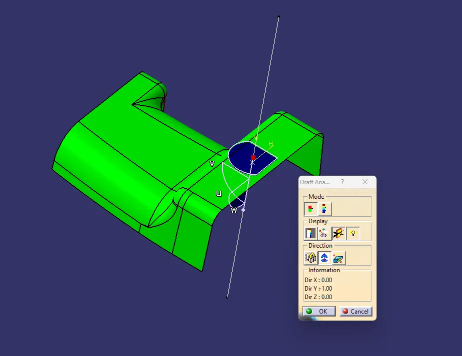
3. CREATION OF A SOLID PART
From the given Class A Surface, we model the Part.
Initially we check if the Class A boundary has any gaps.
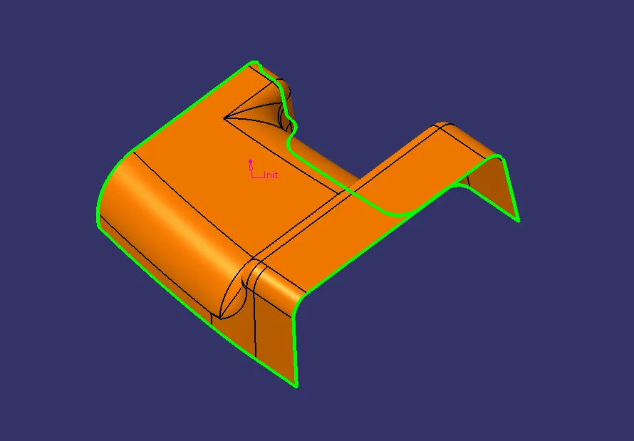
If there are no gaps, we proceed to create the Class B Surface. For that we offset the given Class A Surface downwards by a distance of 2.5mm. This is the thickness of the solid part. While the offset is done, the resulting surface tend to have patches that shows gaps. The gaps are as shown below.
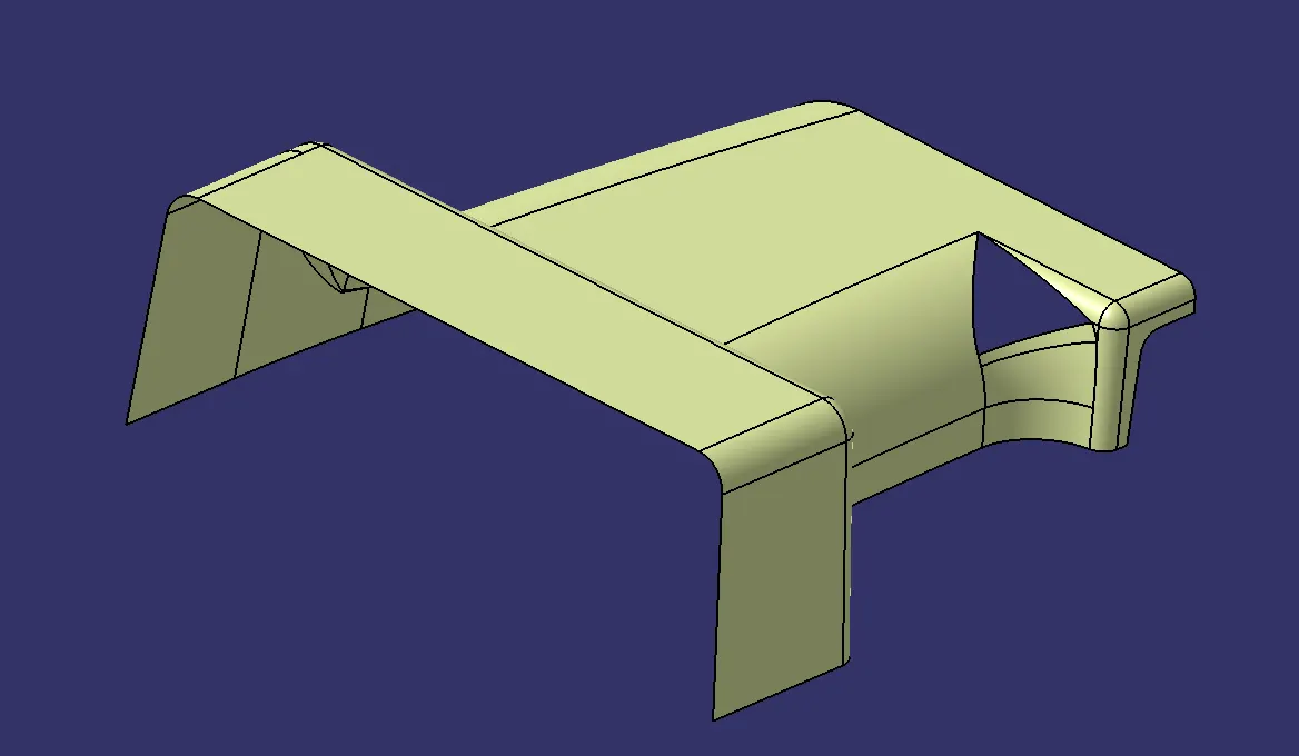
After fixing the gap, the resulting Class B surface is as shown below.
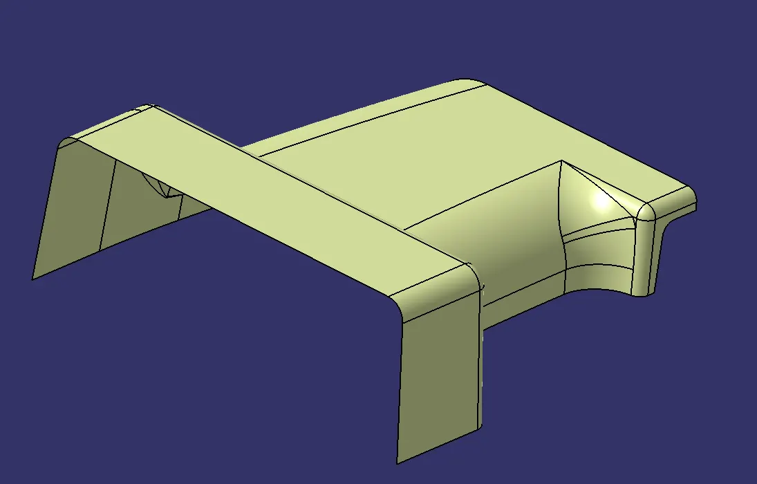
Class A in relation to Class B will look like this,
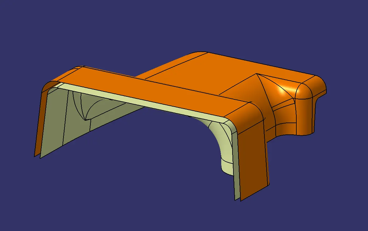
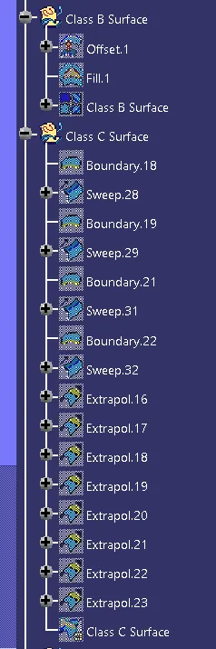
Next step is to create the Class C Surface. Class C surface is the surface that connects both Class A and B. After a series of Boundary Definitions and Sweep commands, we get the Class C Surface as shown in the image below.
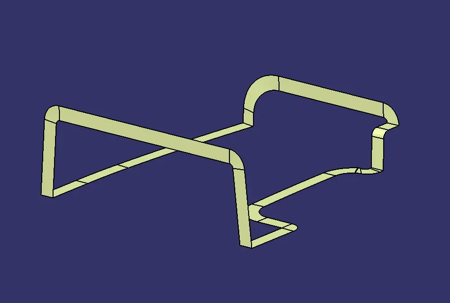
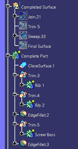
Then the Class A surface and the Class C surface are joined and trimmed with the Class B Surface to get the final surface.
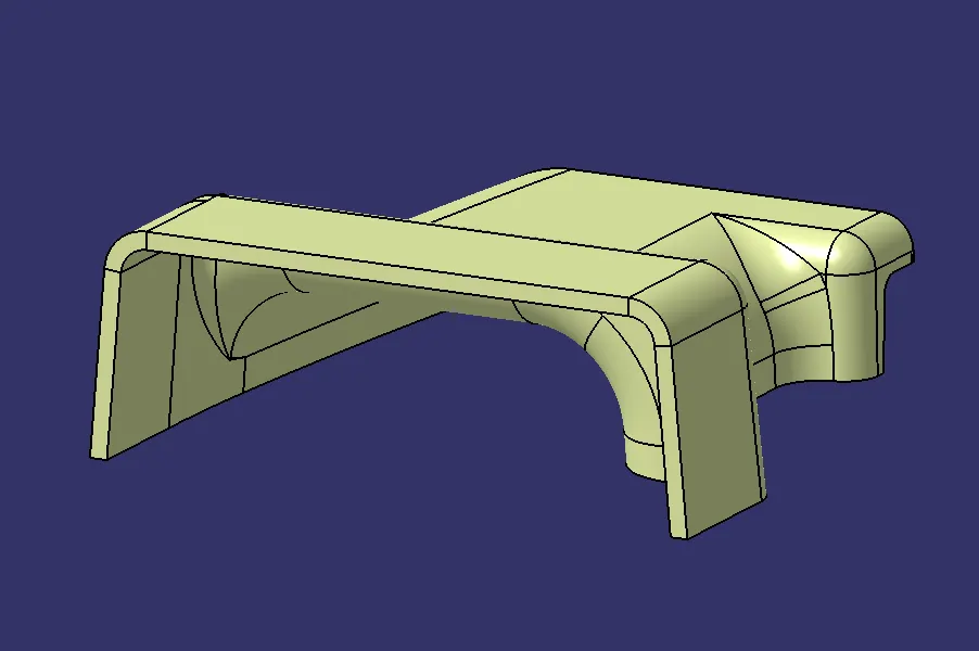
We switch to the Part Design workbench to convert the Surface into a solid body.
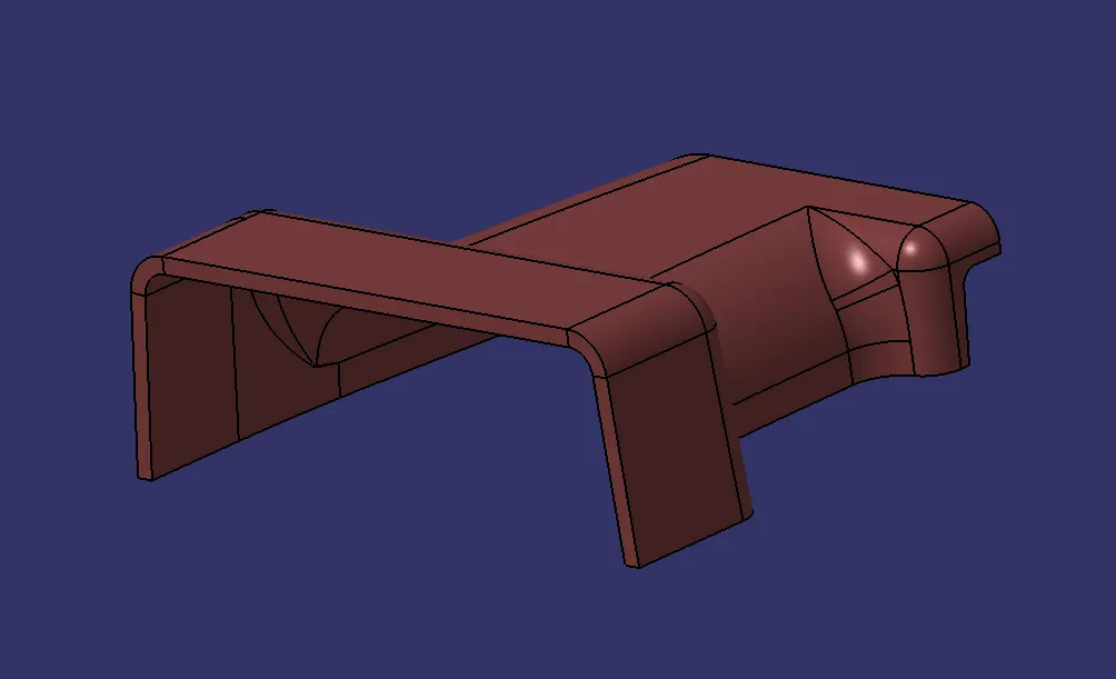
4. CREATION OF RIBS
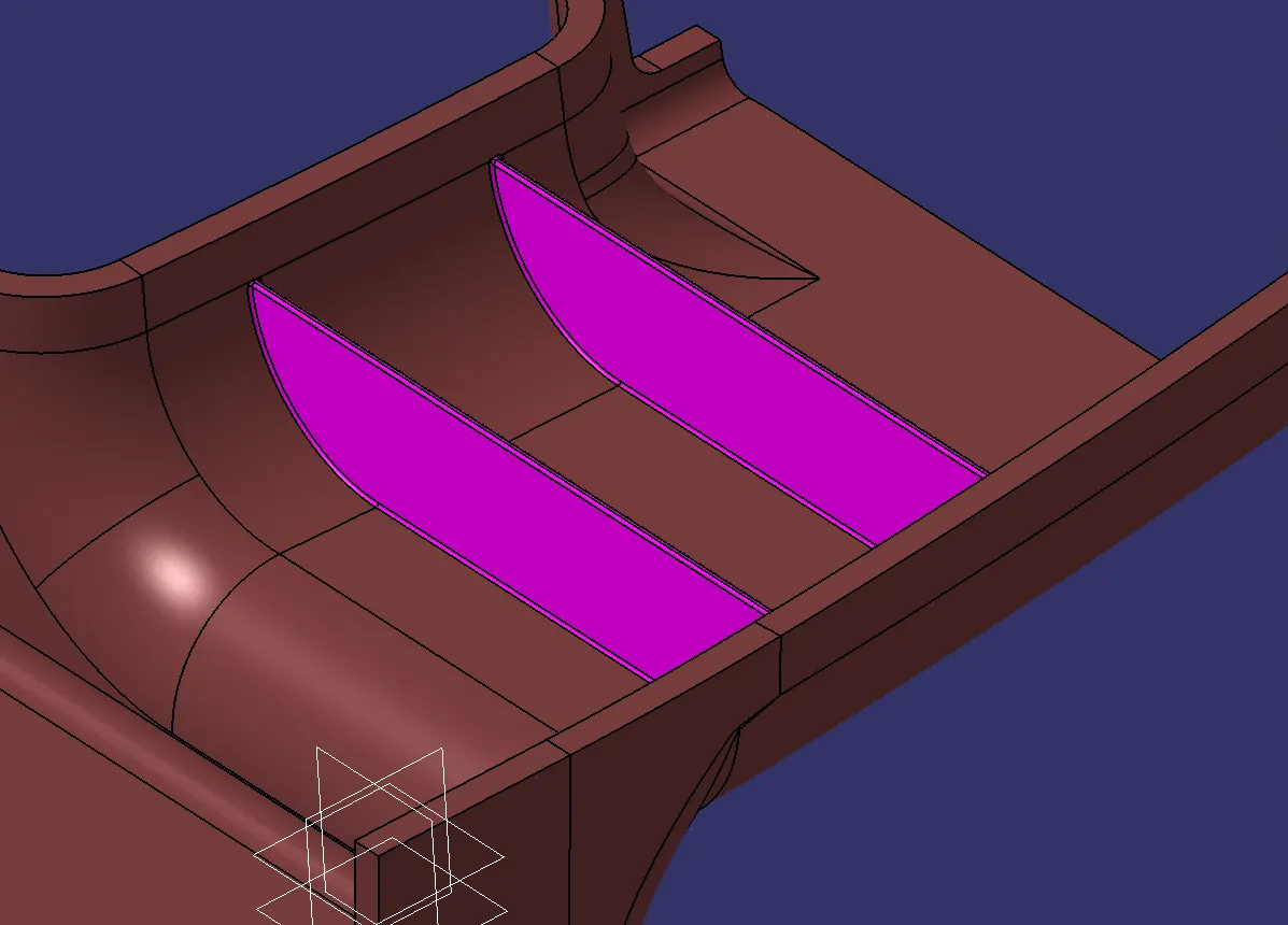
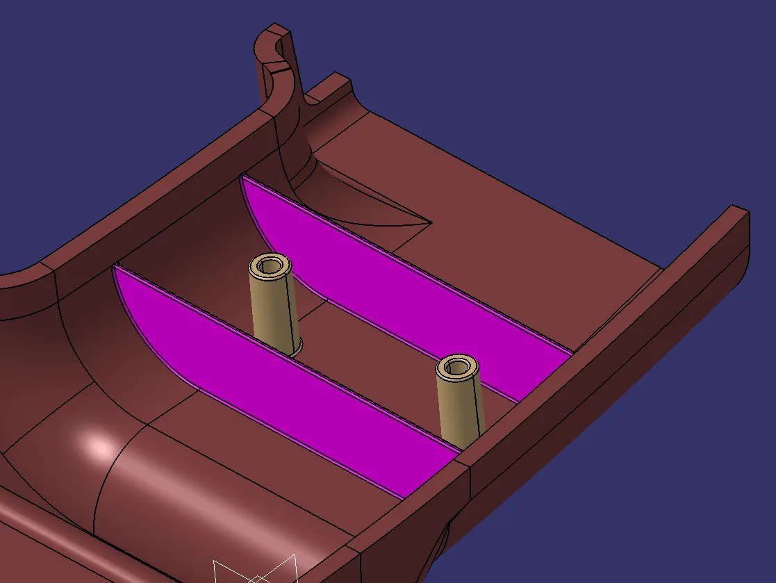
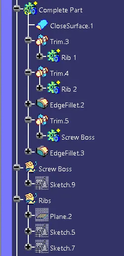
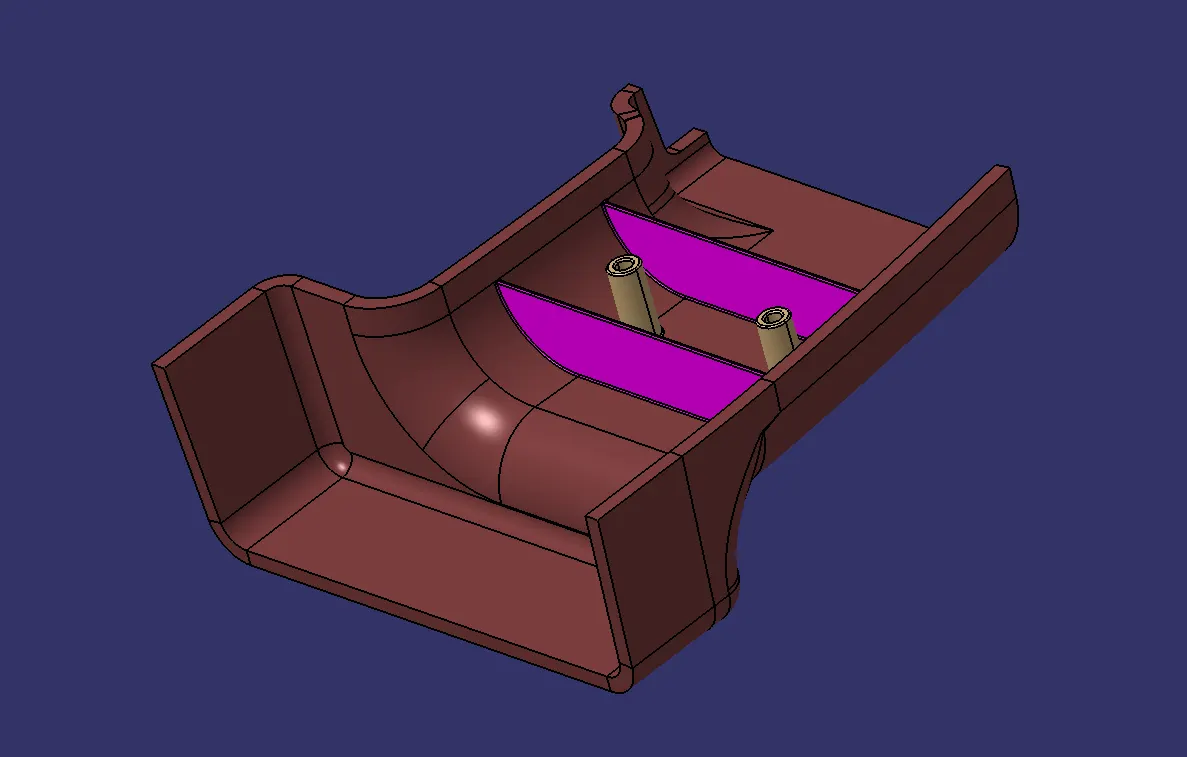
On the solid part we create the Ribs. The thickness of the ribs is around 1mm and the height is around 12.5mm. The ribs are constructed by creating a plane at a height of around 12.5mm from the existing horizontal plane and sketching a line. This line is then extruded into the part. The extruded body is then given a draft of 0.5 degrees and finally Union Trimmed with the Solid body. Fillets of 0.25mm are given in the edges. The ribs are as shown below.
5. CREATION OF SCREW BOSSES
After the creation of Ribs, the next step is to create screw bosses. From the question we infer the values of the inner and outer diameters of the screw bosses to be 2.5mm and 5mm respectively. The sketch required to model the screw bosses are as shown below.
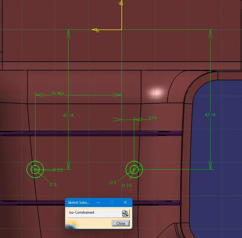
The sketch is then extruded into the solid body and given a draft of 0.5degrees. It is then union trimmed with the solid body to get the combined part.
6. DRAFT ANALYSIS OF FINAL PART
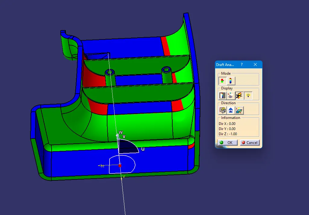
Draft analysis of the final model is done and the result is as shown below.
CONCLUSION
A solid part is modelled from the given Class A surface and Attachment features namely Screw Bosses and Ribs are created on it successfully.
ADDITIONAL IMAGES
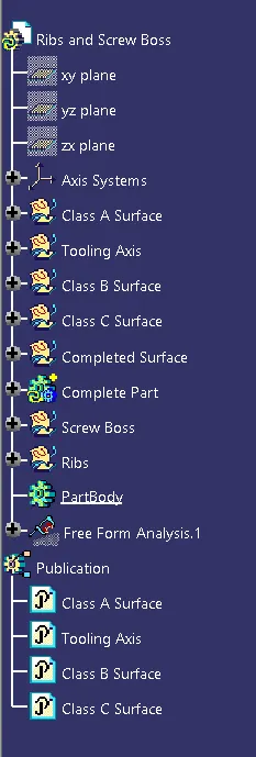
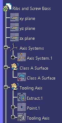
1. DESIGN TREE
2. ISOMETRIC VIEW
3. TOP VIEW
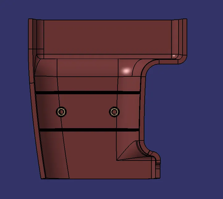
4. FRONT VIEW