Week 10 - Challenge 3 - Door Trim Lower with Engineering Features
DOOR TRIM LOWER WITH ENGINEERING FEATURES
Tooling Axis:
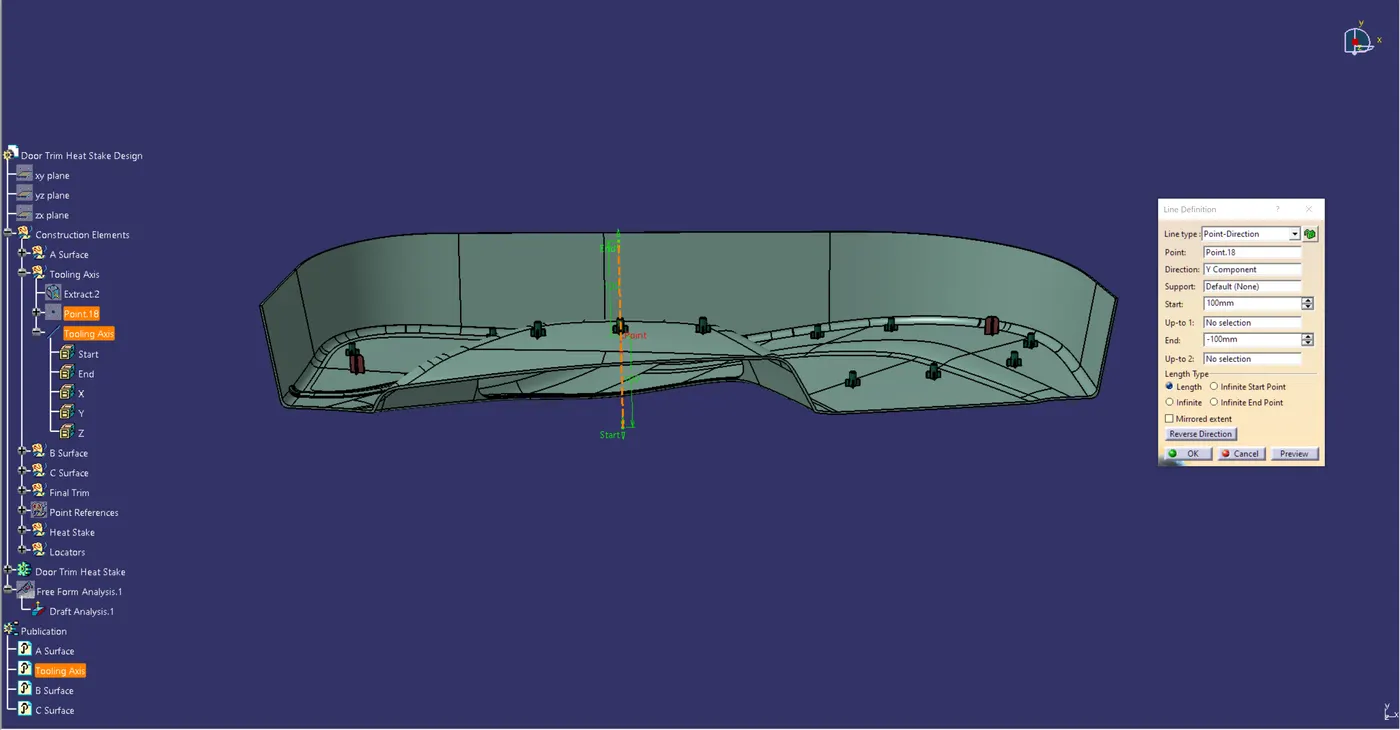
In Order To Generate The Tooling Axis, Take A Surface From Class A, Use The Point Command To Construct A Point In The Middle Of The Surface, And Then Build A Line Through The X-Axis At That Point. Proceed With A Preliminary Examination To Verify Whether The Tooling Axis That Was Generated Is Positioned Correctly, Starting From That Line. If The Tooling Axis Is In The Right Place And Direction In The Draft, Analyze The Surface That Is Indicated In Green On Both Sides Of The Surface.
Draft Analysis :
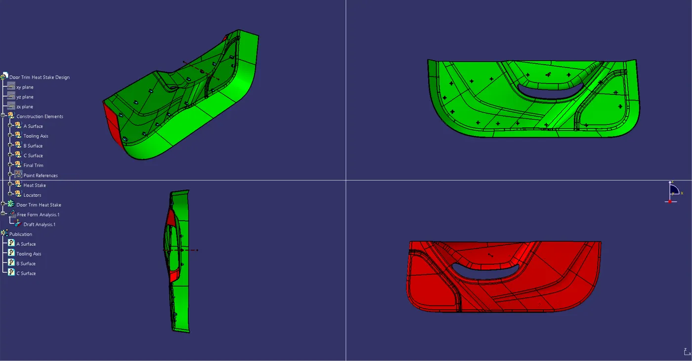
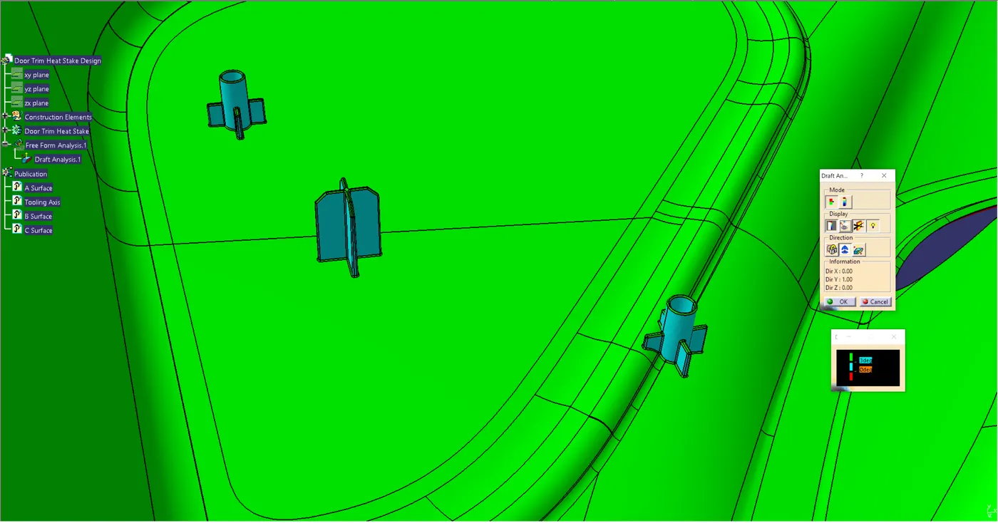
For Cast Or Molded Pieces, The Draft Is The Amount Of Taper Perpendicular To The Parting Line. A Design Feature That Greatly Facilitates A Part's Clean Release From A Mold Is Draft Angles. A Draft Angle Is A Useful Tool For Accounting For Thermoplastic Shrinkage, Which Is A Common Occurrence During The Injection Molding Process For Most Materials. It Is Measured In Degrees (Or, Less Frequently, In Inches Or Millimeters) From The Vertical Axis Of The Mold.
Injection Moulding Design Typically Requires Draft Angles, Yet Some Soft Materials, Like Nylon, Can Get Away With Having Zero Draft Angles. At The Beginning Of The Design Process, All Participants And Stakeholders Should Be Made Aware Of The Draft's Necessity As Part Of The Design For Manufacture. This Enables Consideration Of Design Requirements To Be Taken Into Account And Comprises Product Designers, Design Engineers, Etc. Any Draft Is Always Preferable To None At All.