Week 10 - Challenge 3 - Door Trim Lower with Engineering Features
Week 10 - Challenge 3 - Door Trim Lower with Engineering Features
DOOR APPLIQUE STEP FILE USED
THICKNESS 2.5mm,
Aim:
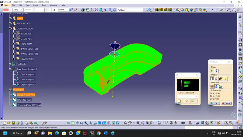
Create the Door Trim Lower Plastic component through the given Class-A surface. To begin with, the tooling axis for the given Class-A Surface should be created meeting the requirements of the draft angle and at the end perform the Draft analysis on the model.
Create the Heat Stakes and the locators considering the design rules mentioned in the video for the door applique.
Tooling Axis Creation:
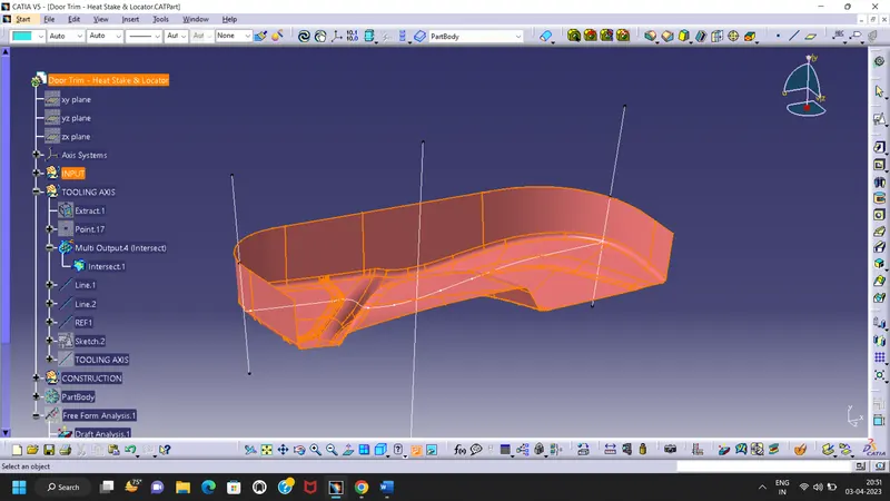
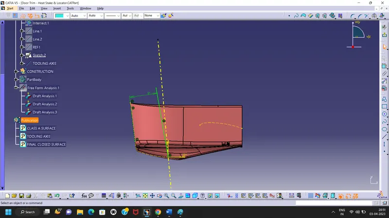
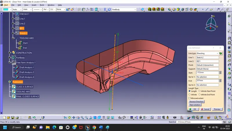
Here i have used bisecting method to create Tooling axis,
- Firstly i had intersect line through had create dummy axis line via bisecting line create option.
- Second sketch create as per the another face intersection project through 3 Dgree line created
- Then finally bisecting line inputs of through above created 2 lines.
- Now finally created line as considered Tooling Axis of my component.
Class A surface Draft Analysis:
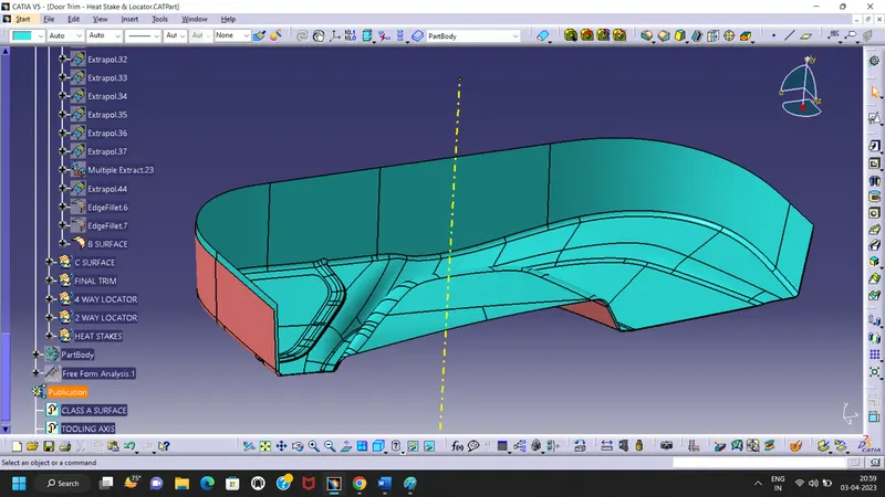
B Surface creation:
To create B surface i just offet the Class A surface.
- Then I started to close ass the patches to one by one.
- Here I got 3 patches to close and i worked through using the extract, multi extract, extrapolate, untrim, Join, multi section surface & trim tools to resolve all the patches.
- Then I got trim together all to make final B surface and fillet provided as input gotton by Class A surface.
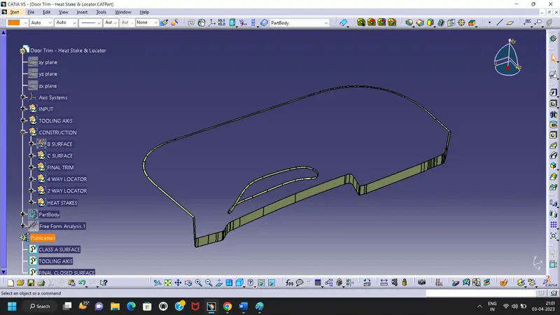
C Surface creation:
To create C surface create boundry
- Then sweep done with tooling axis guide curve provision.
- all muliextract sweep as per tooling axis and reference to the surface.
- then join together to create C Surface.
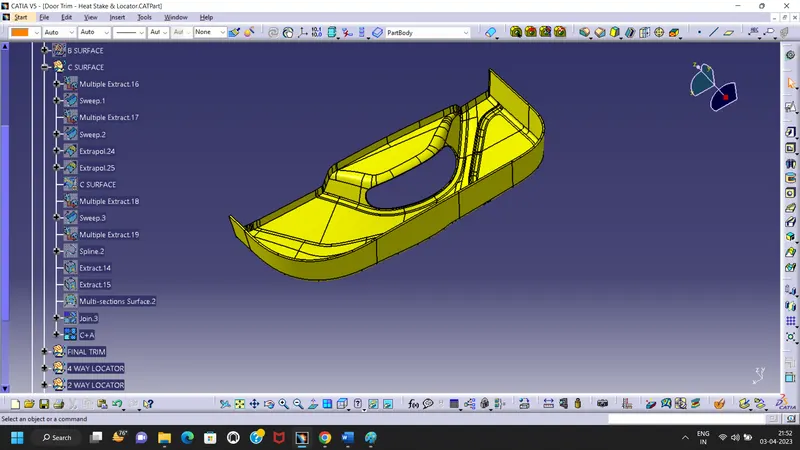
C+A Surface creation:
I have joined the C with Class A and created the C+A Surface.
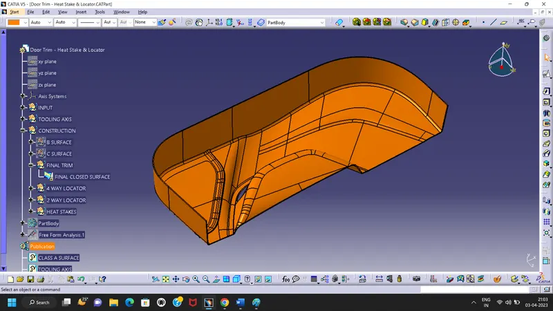
Closed surface creation:
I got trim together the Class B with C+A surfaces and i got final closed surface.
Closed surface Draft Analysis:
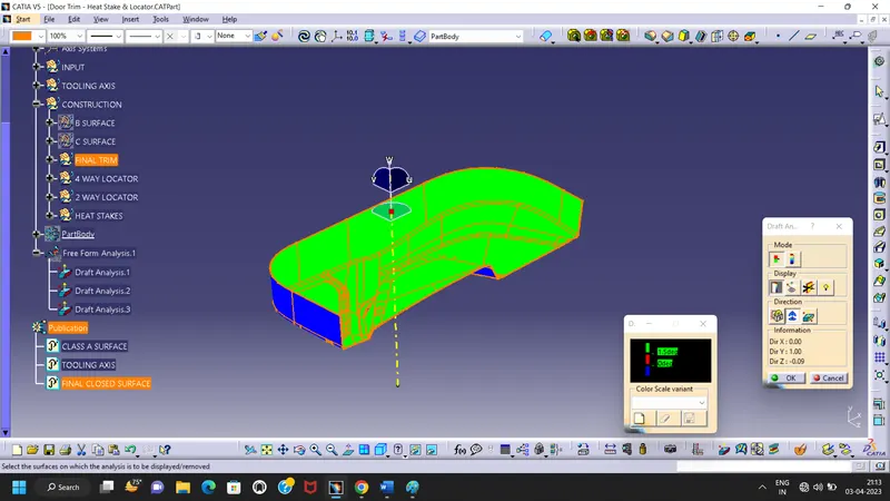
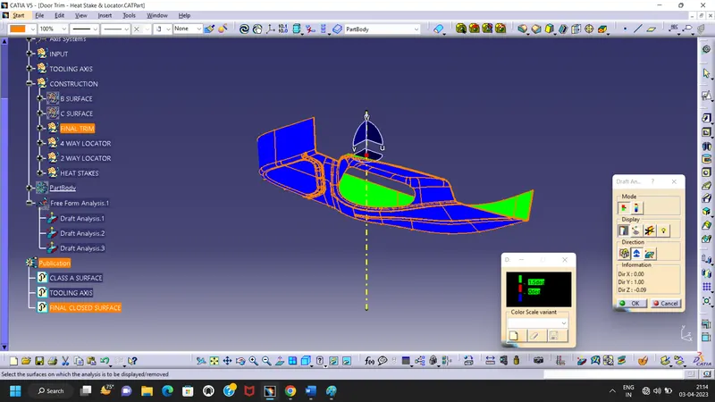
Part Body creation with input of Closed surface:
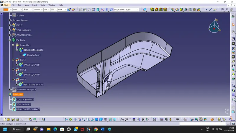
Locator & Heat Stake Design:
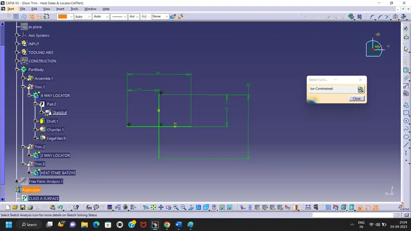
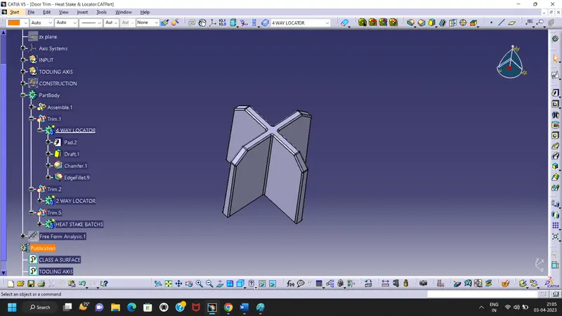
4 Way Locator Design:
Sketch done at projection points given along with class A.
Then Pad then Draft for 0.5 Dgree and fillet provided upto 0.25 ~0.3mm.
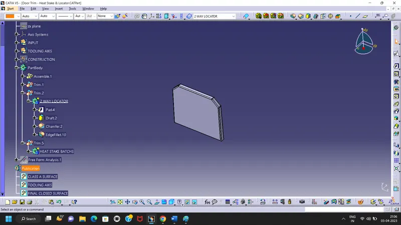
2 Way Locator Design:
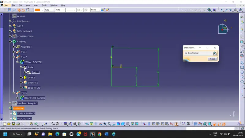
Sketch done at projection points given along with class A.
Then Pad then Draft for 0.5 Dgree and fillet provided upto 0.25 ~0.3mm.
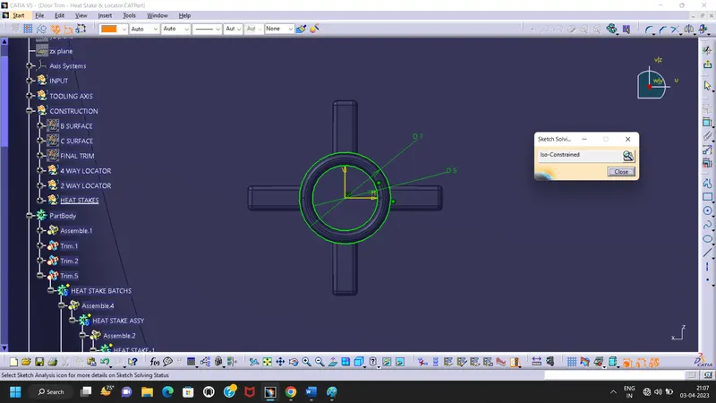
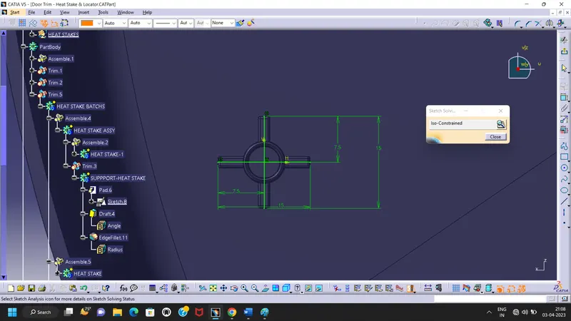
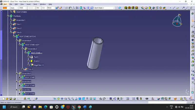
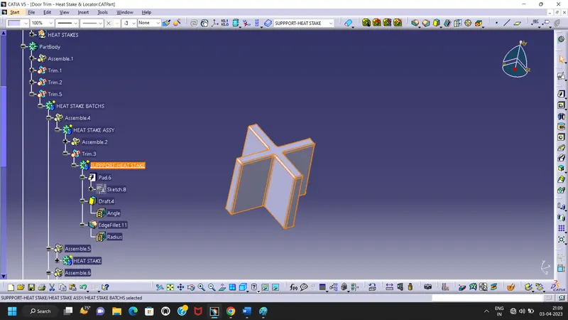
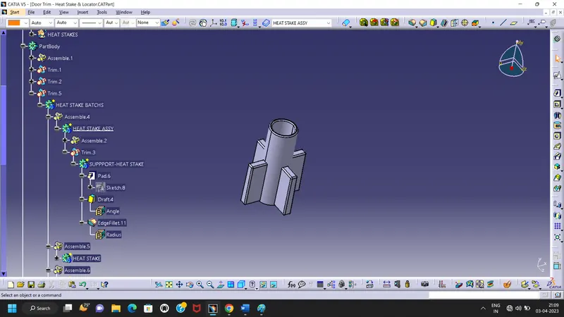
Heat Stakes design:
Stake sketch created by the dimension taken from the videos.
and every heat stakes have provided draft angle 0.5Dgree and fillets as same as locator fillets.
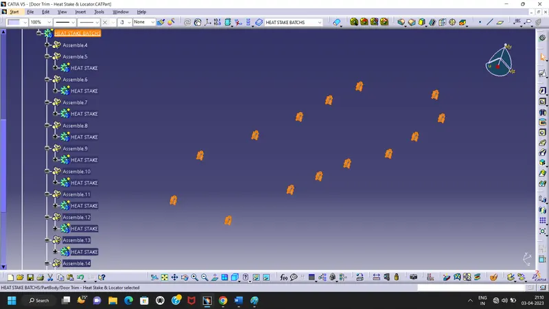
Boolean Operations for Assemble:
All solid part assemble by boolean operations assemble, untrim the add as required operations.
Now final part body created with locators and heat stakes.
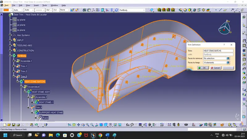
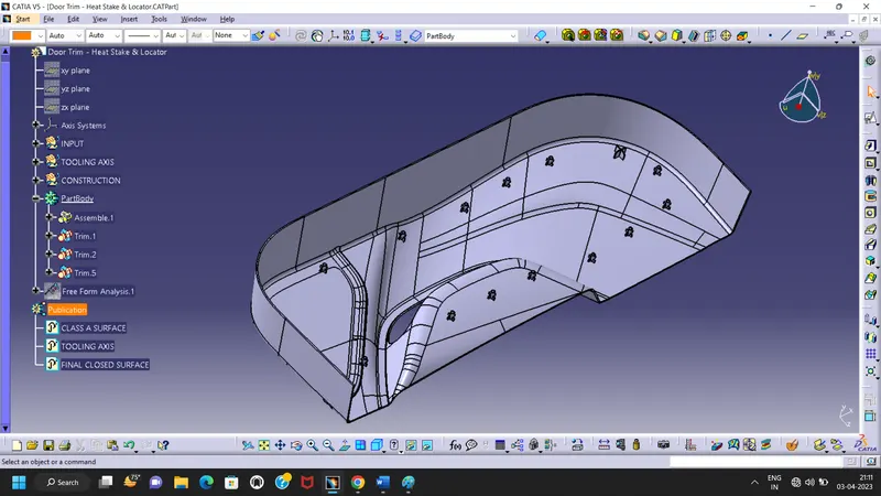
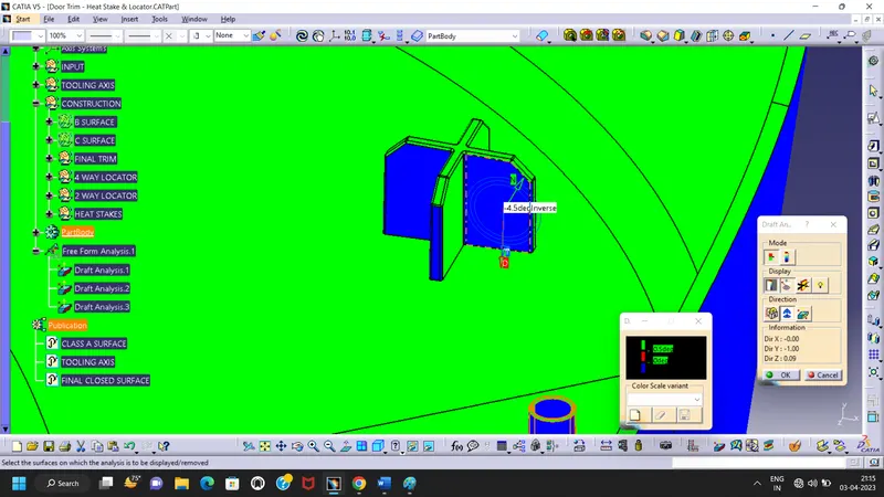
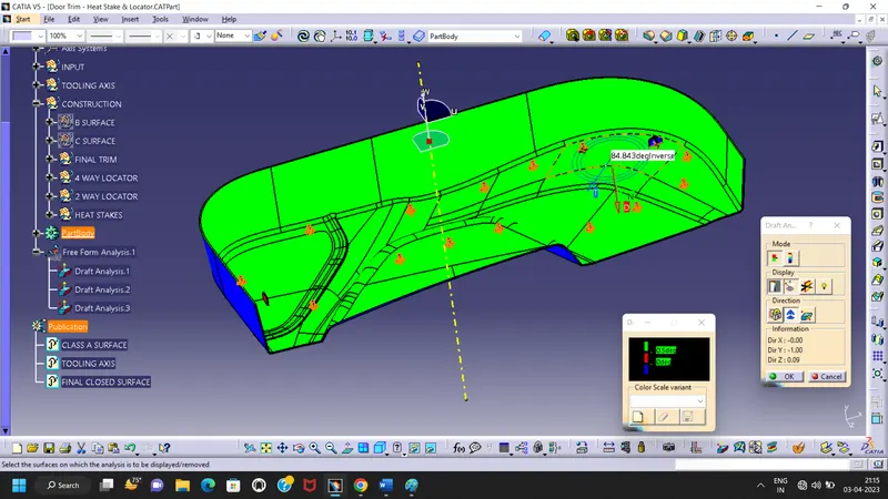
Draft Analysis for Final Part body & Locator & Heat stakes:
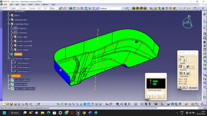
Views:
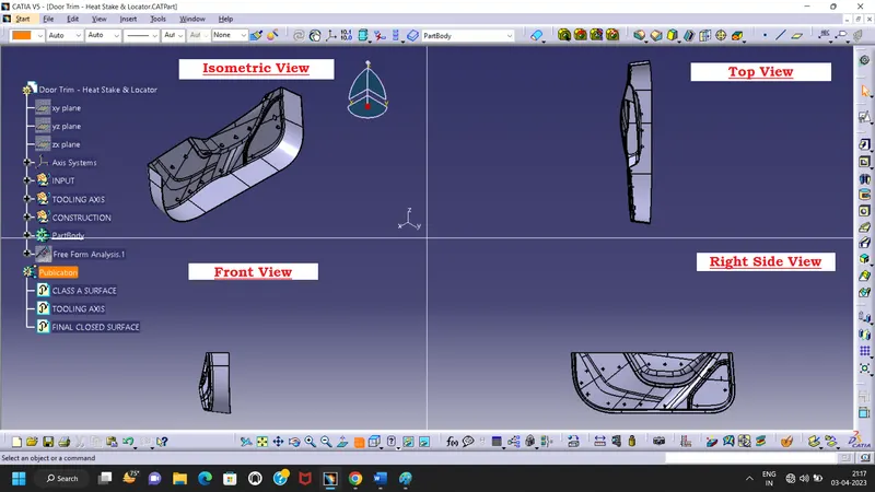
Other orientation views:
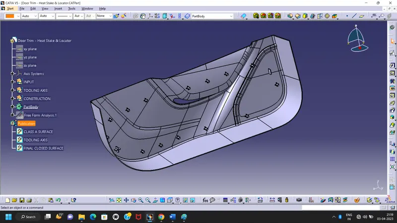
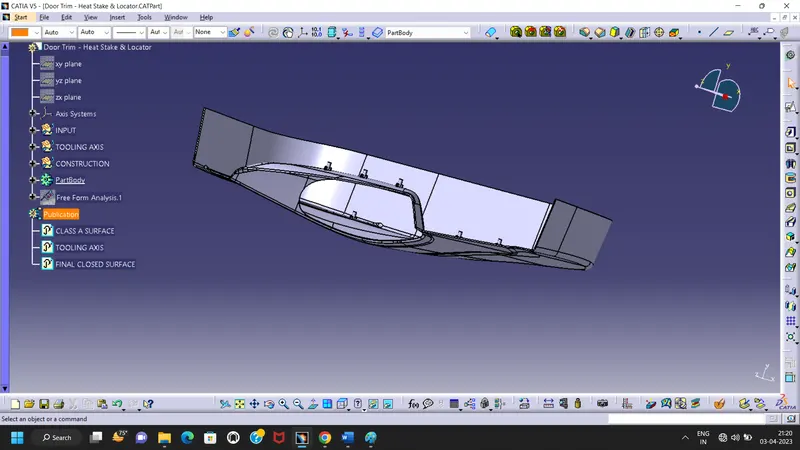
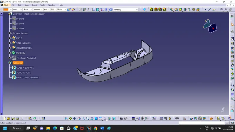
Final Preview Part Body:
Note: I herewith enclosed the door trim applique CAT Part with creation of 4 way & 2 way locators with Heat stakes in Zip format.