Week 8 - Challenge 4 - Bumper
Week 8 - Challenge 4 - Bumper
Inputs:
- Class A Surface of the Bumper (STEP Used).
- Thickness of Plastic Part - 3 mm.
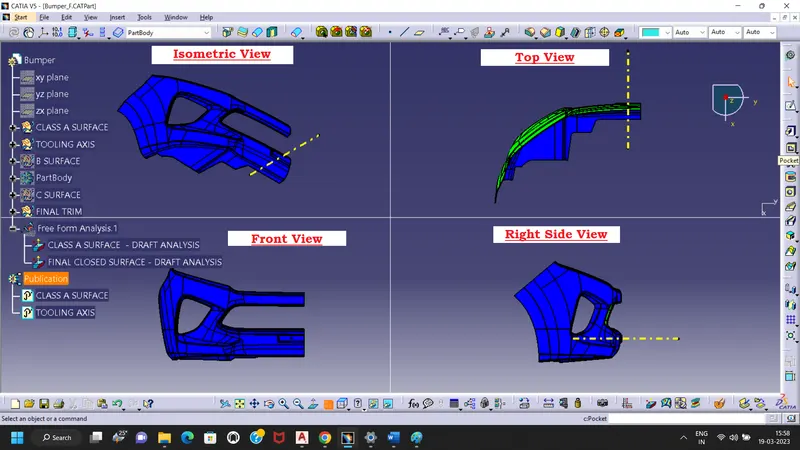
Screenshots of the Draft analysis report for both the given Class-A surface and the final plastic component:
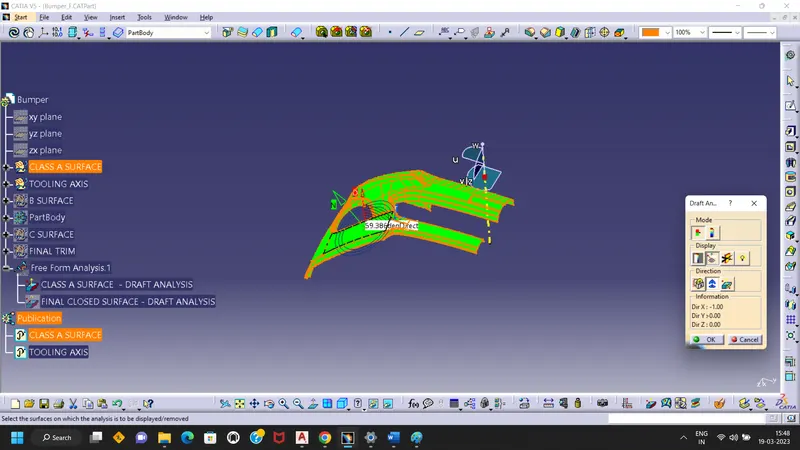
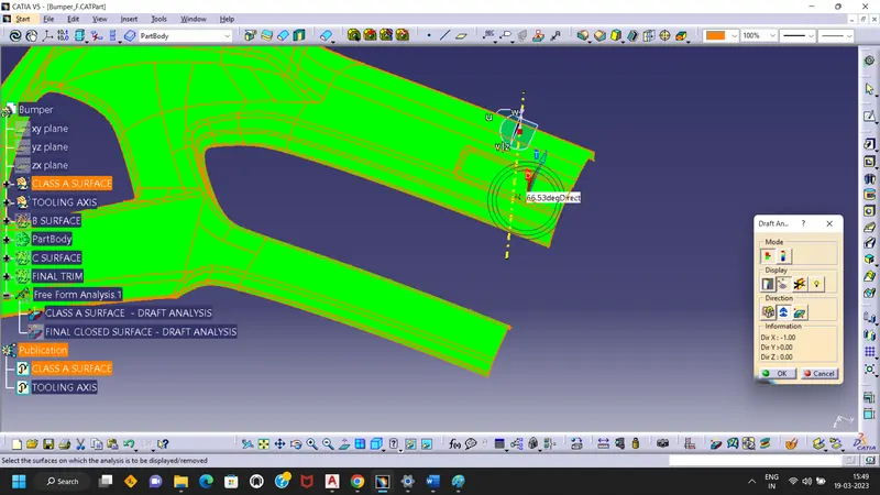
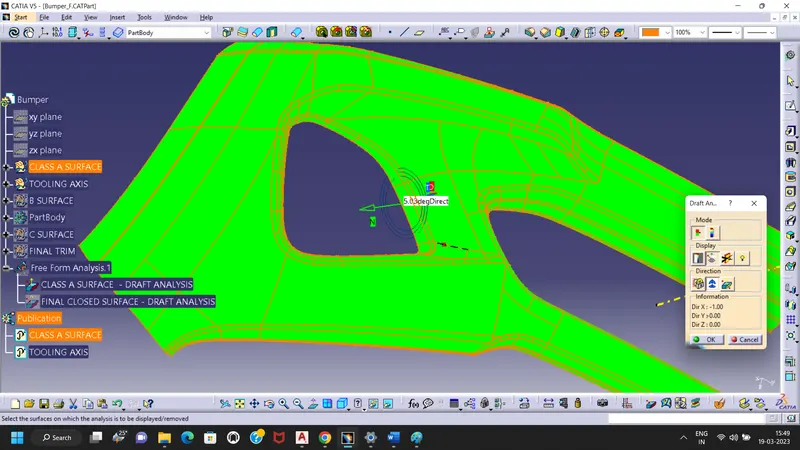
Class A Surface Draft Analysis Report:
- In is given class A surface dont have any below 3 Dgree draft or any other negative value.
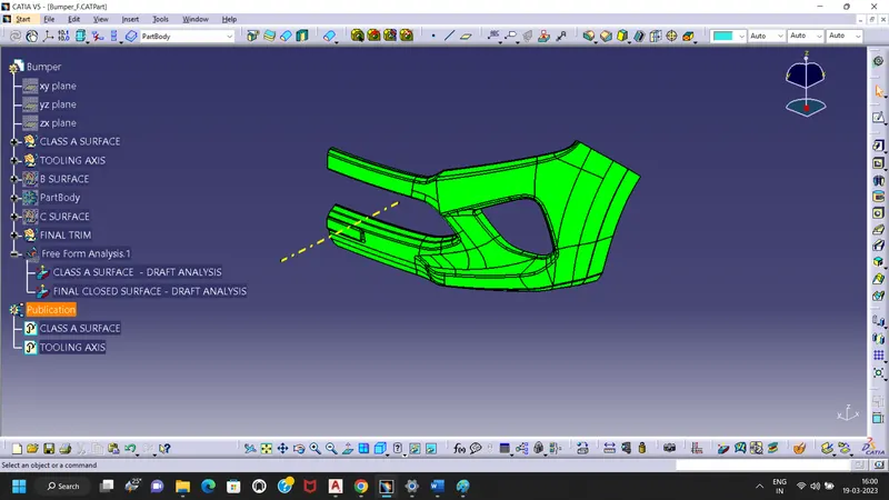
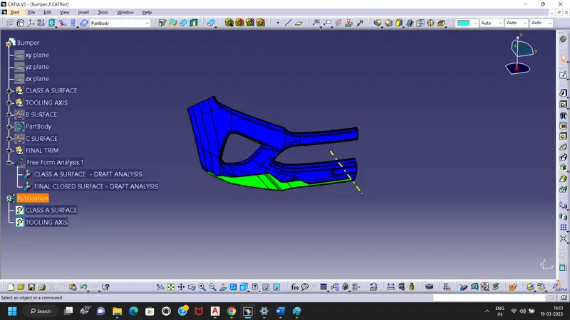
Here below 3 various face angle verfied images as below by draft angle analysis method,
Final Product Closed Surface Draft Analysis Report:
Here below 3 various face angle verfied images as below by draft angle analysis method,
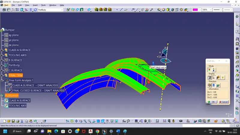
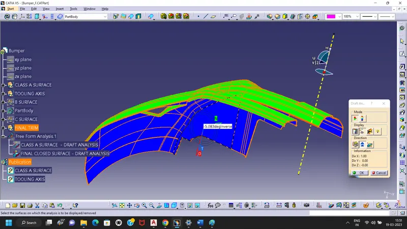
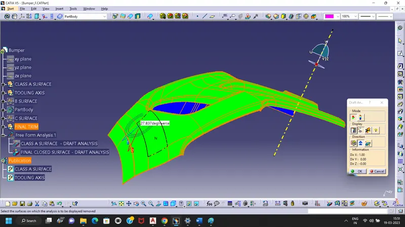
Image of the complete Draft analysis:
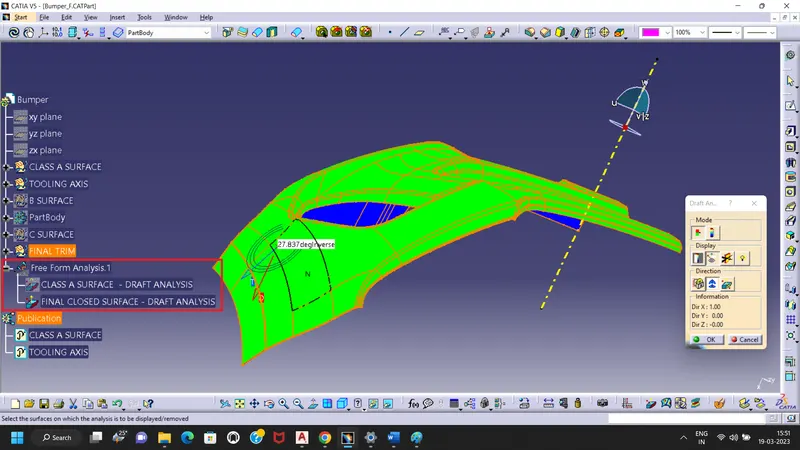
Images of the color scale variant:
- Green color is indicating upto 3 Dgree
- Red color is indicating upto 0 Dgree
- Blue color is indicating upto Below 0Dgree or Negative Value.
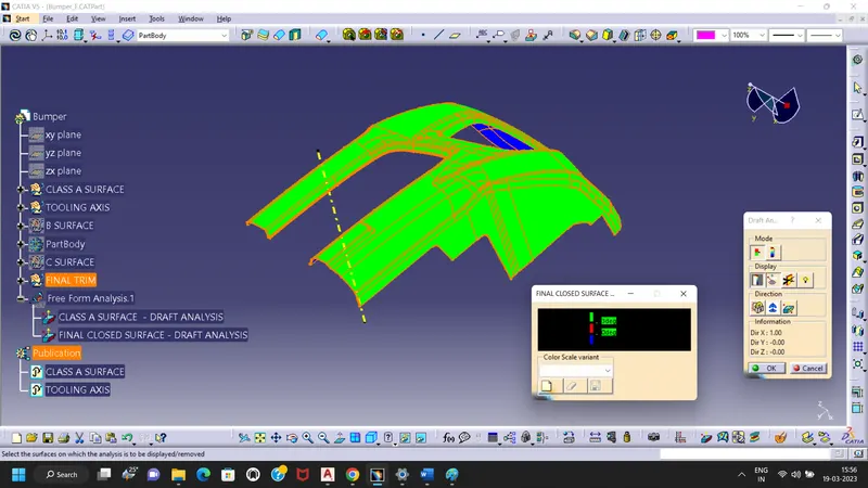
Screenshots of the solid model with the proper color code of the draft angle in various orientations and various views:
Detailed Report of the Bumper:
I have start work with inputs of Class A surface which received(STEP Used).
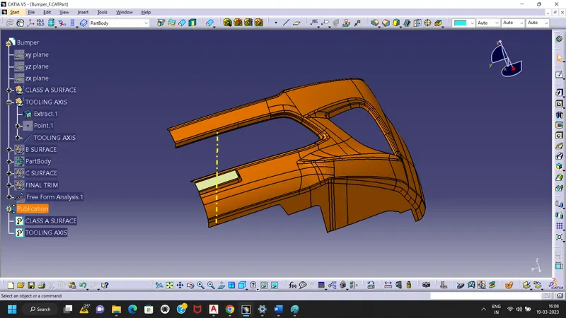
Tooling Axis Creation:
- In this Class A surface have flat face extract and point created.
- Normal line created with select point and perpendicular line created for the surface.
- This line consider as tooling axis.
- later I have done draft analysis for the class A surface also verified the created tooling axis.
Below Image for the Tooling Axis create Screen shot,
Class B and Class C Surface Create:
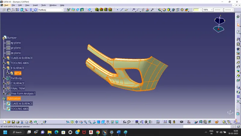
- In order to creating the B surface, i just offset the Class A but i get some error of gap then i just accept with the offset surface.
- first remove unwanter surface with help of tool multiextract then boundary extracted then extrapolate on both and i just did trim to created the B Surface.
- the measure fillet size on all the radius portion and i provided fillet on created B surface at required portions.
- then finally i go B surface.
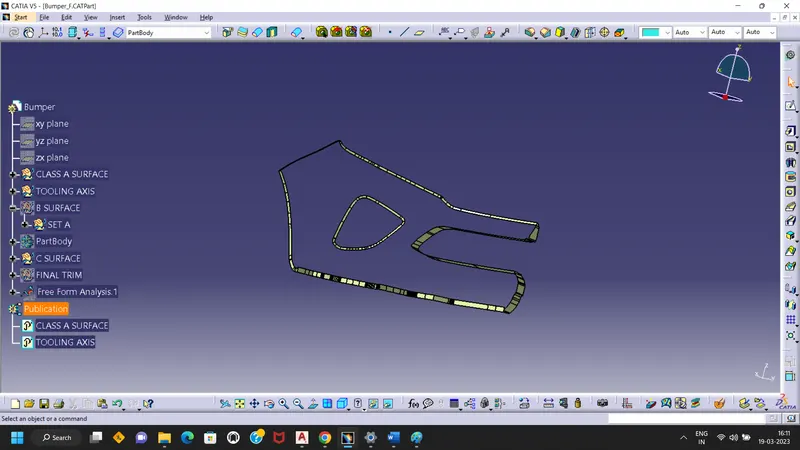
- To craete C surface, I had followed 2 type of sweep first one is draft angular sweep second one is sweep with reference surface.
- accourding to the b surface needs i sweet the extracted boundary on 5 batches then i just extrapolate at required portion of the created surface for C then trimed as required.
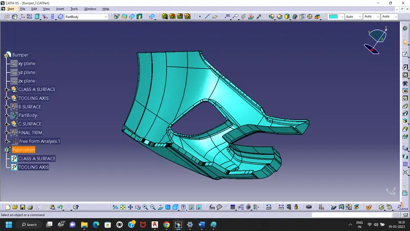
- Then finally i got join the Class A with C surface to create A+C.
B Surface Image:
C Surface Image:
C+A Surface Image:
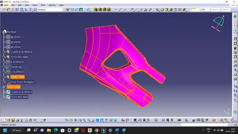
Final Trim:
Once all to gethered - B & C Surfaces.
Have join the C surface with Class A and got join as per above picture.
Then later B Surface trim with Join to make closed surface.
Final Trimed image as below,
Solid Body:
Final solid created by inputs of the above final trim Bumper Designed surface.
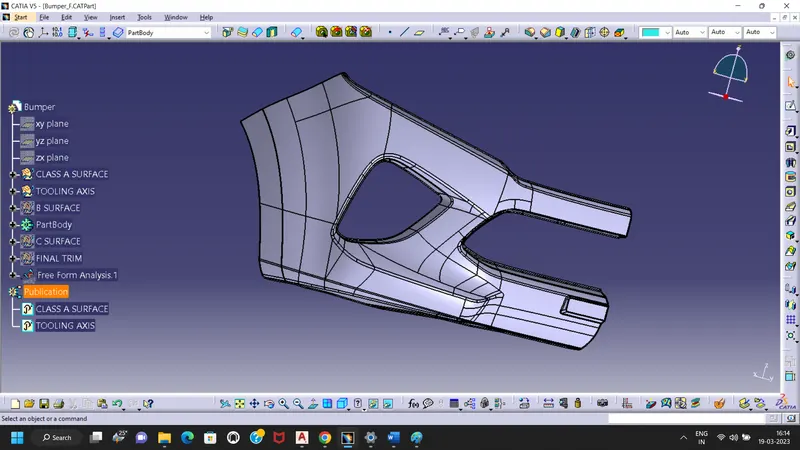
The above processed have followed to make the B & C surfaces for final product designing.
Note:
- I herewith enclosed the final CAT Part in Zip format.
- I request to use hide/show to check the hidden surfaces and draft analysis report into the CAT file.