Week 8 - Challenge 3 - Coin Holder Design
Week 8 - Challenge 3 - Coin Holder Design
Inputs:
- Class A Surface of the Coin Holder (STEP Used).
- Thickness of Plastic Part - 2.5 mm.
Screenshots of the Draft analysis report for both the given Class-A surface and the final plastic component:
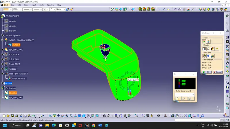
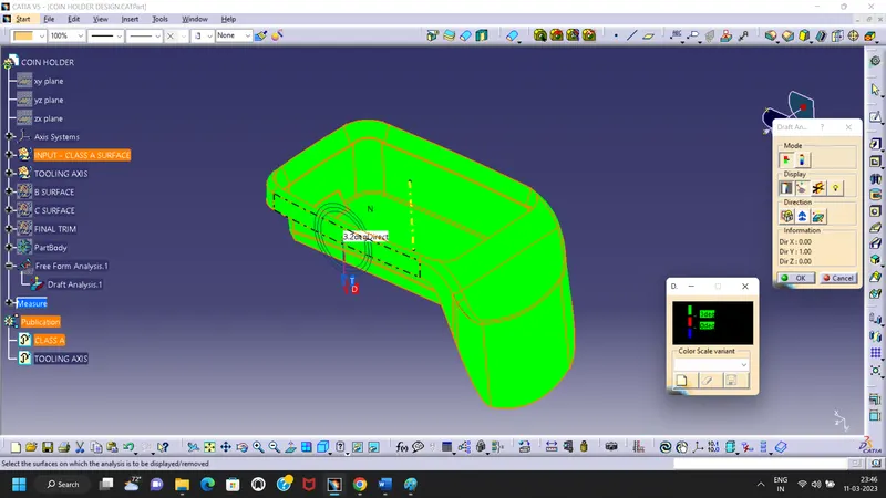
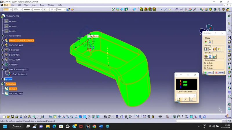
Class A Surface Draft Analysis Report:
- In is given class A surface dont have any below 3 Dgree draft or any other negative value.
Here below 3 various face angle verfied images as below by draft angle analysis method,
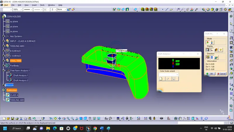
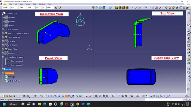
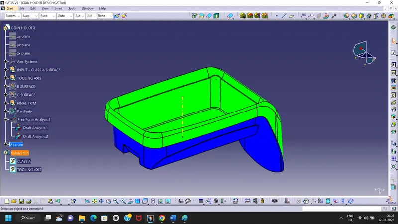
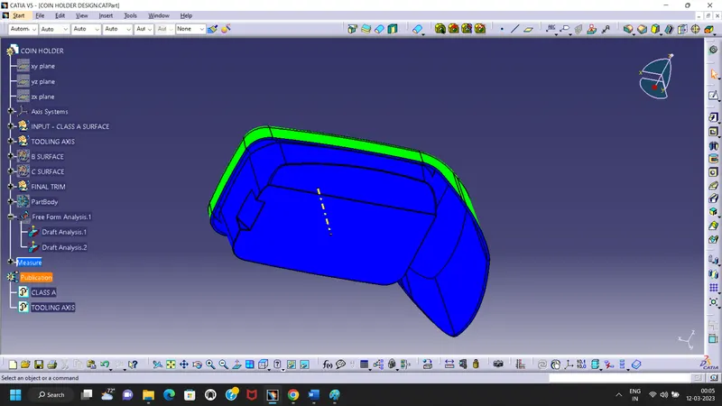
Final Product Closed Surface Draft Analysis Report:
Here below 4 various face angle verfied images as below by draft angle analysis method,
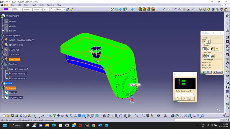
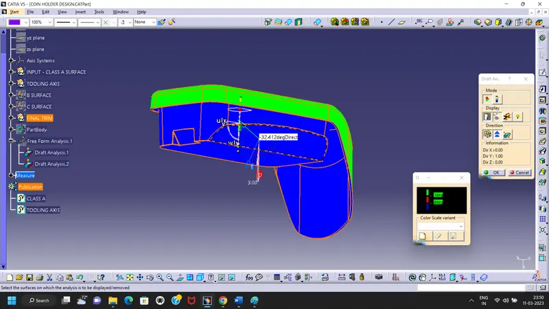
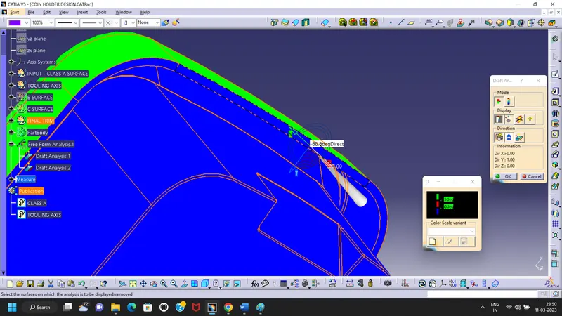
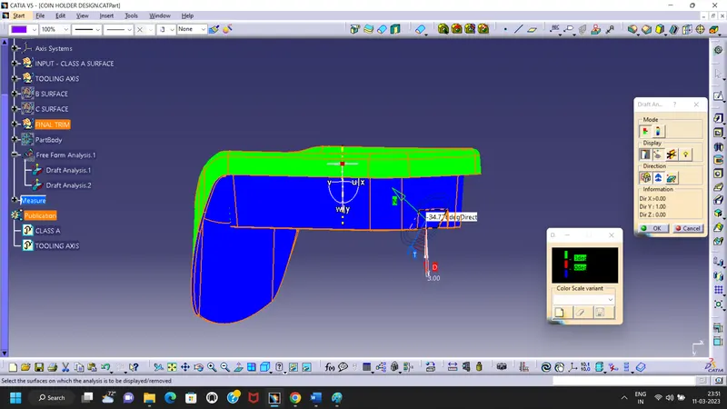
Image of the complete Draft analysis:
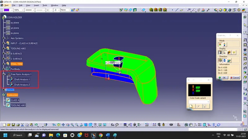
Images of the color scale variant:
- Green color is indicating upto 3 `Dgree`
- Red color is indicating upto 0 `Dgree`
- Blue color is indicating upto Below 0`Dgree` or Negative Value.
Screenshots of the solid model with the proper color code of the draft angle in various orientations and various views:
Detailed Report of the Coin Holder Design:
I have start work with inputs of Class A surface which received(STEP Used).
Tooling Axis Creation:
- In this Class A surface have flat 0 Dgree Base profile and 90 Dgree walls then different varies shapes.
- So here i have extract the base surface then used normal to, on surface point create then on later normal line created as Tooling Axis.
Below Image for the Tooling Axis create Screen shot,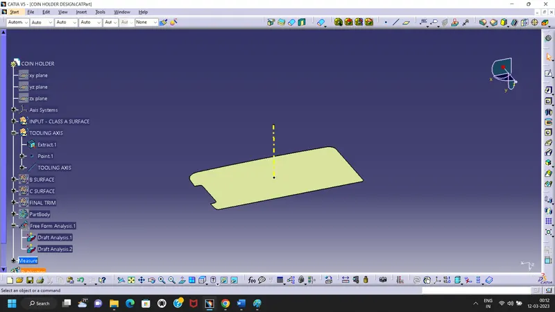
Class B and Class C Surface Create:
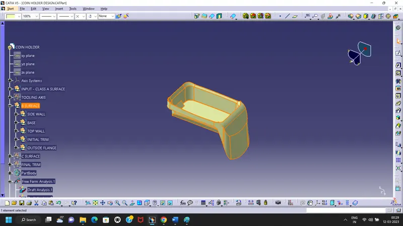
- In order to creating the B surface, at first I have segrigate on the construction of bsurface under 5 batch.
- First one is considering a side wall creation, by extracting the all 4 the walls then untrim those all then extrapolate as required distance.
- Then offset the walls and trim it all the walls to create single side wall surface creation.
- Then Edge fillet done with inspecting the Class A radius input provided with reducing the thick value on the radius before feed the "R" Value.
- Once created the Side Walls then Base and Top wall created as same as extract, unitrim and extrapolate method then all trim together as final trim separte.
- Outer flange made and offset inside then same way trim together the made all trim together.
- once all made the fillet provide as required places form the class A surface Fillet inputs.
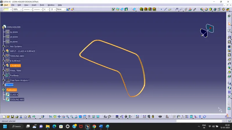
- Then to create the C surface class A top boundary extracted then have created sweep with taken reference of class A surface Top side walls.
- Then 90 Dgree angle based sweep create upto 4mm.
- Once created the C surface just color updates done for easy identifications.
B Surface Image:
C Surface Image:
Final Trim:
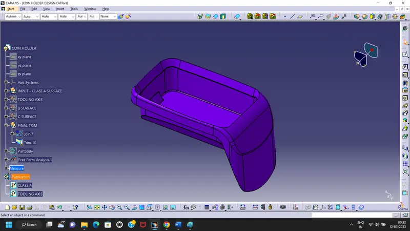
Once all to gethered - B & C Surfaces.
Have join the C surface with Class A and got join.
Then later B Surface trim with Join to make closed surface.
Final Trimed image as below,
Solid Body:
Final solid created by inputs of the above final trim Coin Holder Designed surface.

The above processed have followed to make the B & C surfaces for final product designing.
Note:
- I herewith enclosed the final CAT Part in Zip format.
- I request to use hide/show to check the hidden surfaces and draft analysis report into the CAT file.