Week 10 - Challenge 3 - Door Trim Lower with Engineering Features
AIM:-
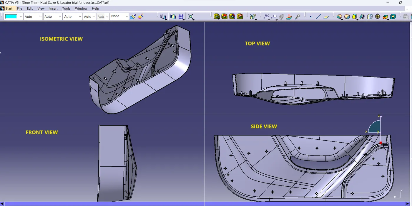
To Create the Door Trim Lower Plastic component through the given Class-A surface. To begin with, the tooling axis for the given Class-A Surface should be created meeting the requirements of the draft angle and at the end perform the Draft analysis on the model & Create the Heat Stakes and the locators considering the design rules mentioned in the video for the door applique.
DESCRIPTION:-
- Used Positioned sketch
- Sketches are Iso-Constrained
- Used the given points in the model to create the locators and Heat stakes
- Refer to the below-given image for more details
- Ensured Proper Tree Structure
- Geometrical sets had a proper name based on the sketches present inside of it
- All the sketches are created under the Geometrical set
TOOLING AXIS:-
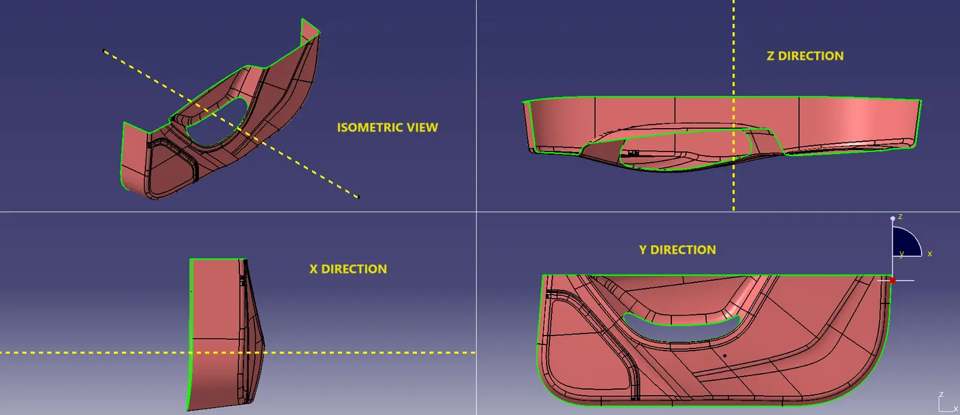
As mentioned in the above image the y axis is looking feasible and suitable for tooling axis compared to all other directions for the door trim .
DRAFT ANALYSIS REPORT OF CLASS A:-
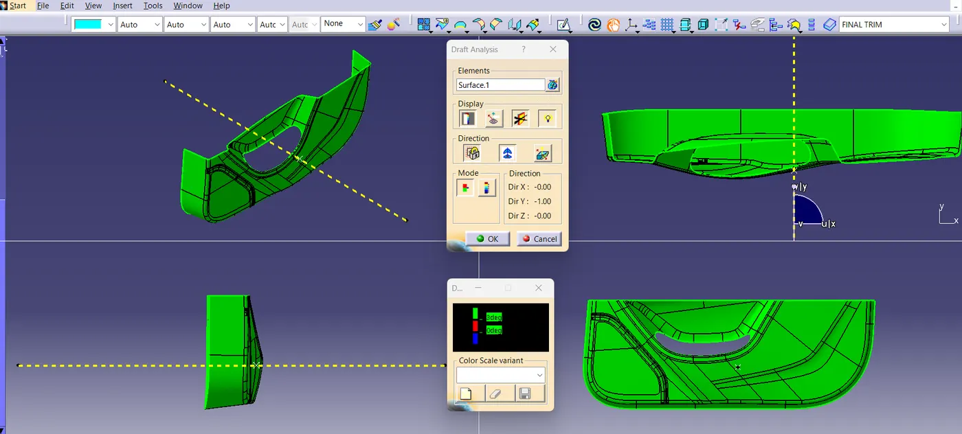
The Draft analysis is carried out along the tooling axis direction and the given Class A suface is clearing the draft analysis of nominal draft 3deg.
DRAFT ANALYSIS OF SOLID BODY:-
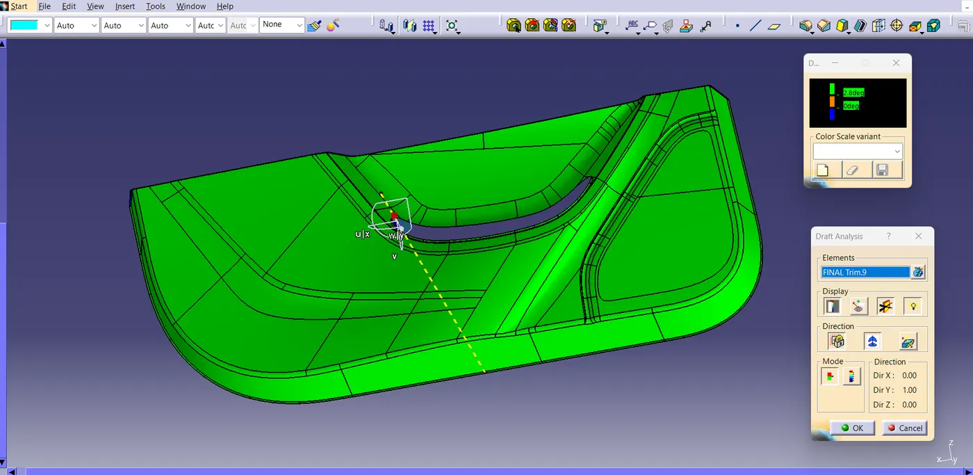
The thickness of the door trim is 2.5mm and Class B surface clearing the draft analysis.
CLASS C SURFACE DRAFT ANALYSIS REPORT:-
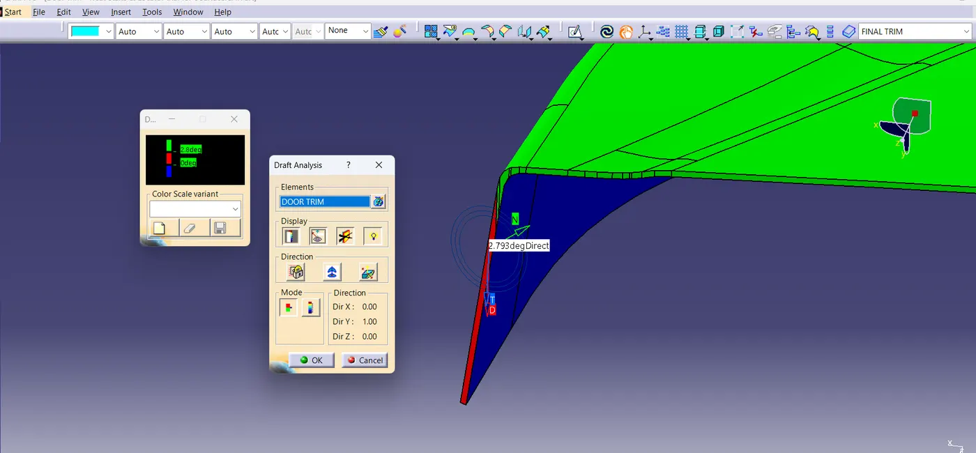
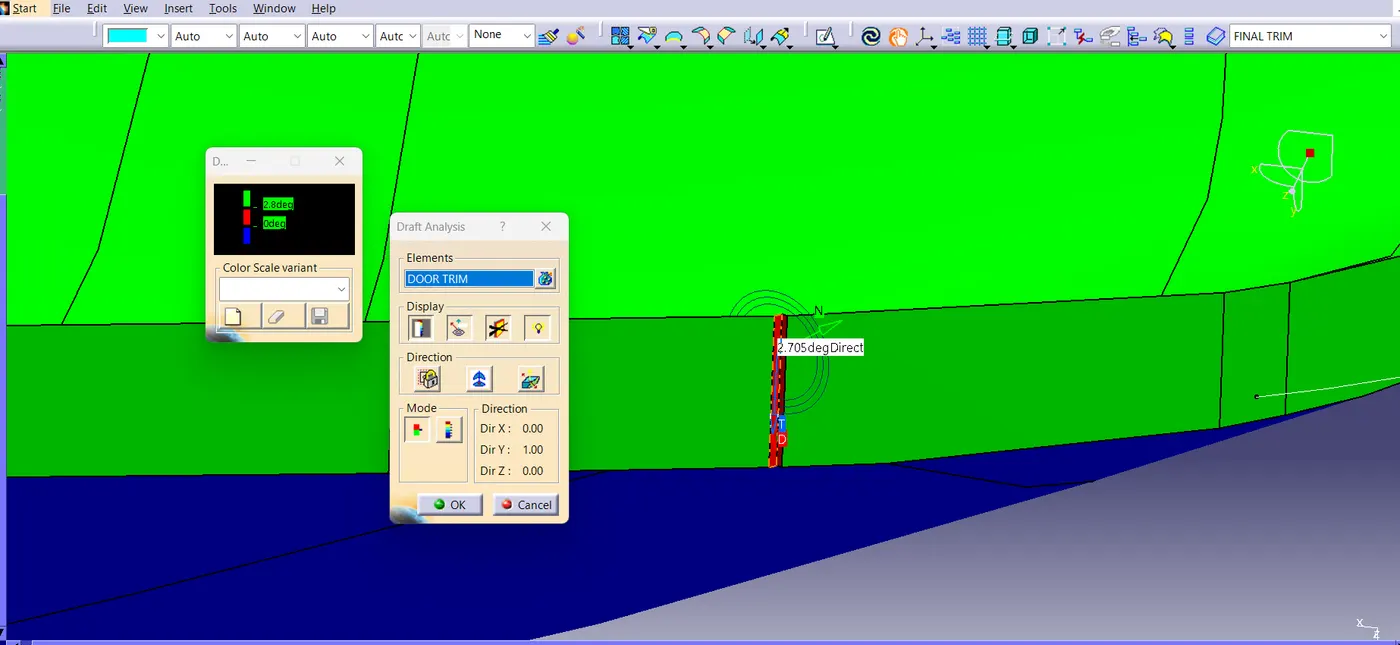
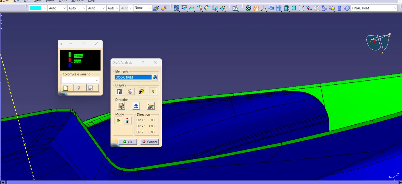
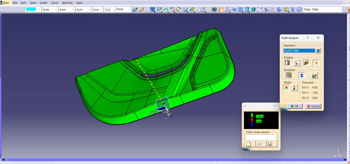
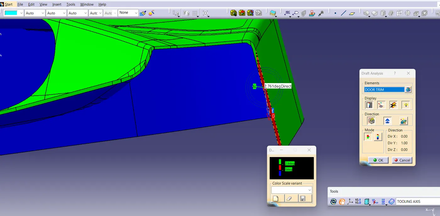
Most of the class C surface were clearing in draft analysis some of the verticle surfaces which is perpendicular to tooling axis will not clear the draft analysis as i mentioned in above images. Surfaces which are perpendicular to tooling axis are created using sweep with reference surface.
HEAT STAKES & 4 WAY LOCATERS DRAFT ANALYSIS REPORT :-
The Heat stakes & 4 way locaters are created using the design rules mentioned in the video and also it is clearing draft analysis.
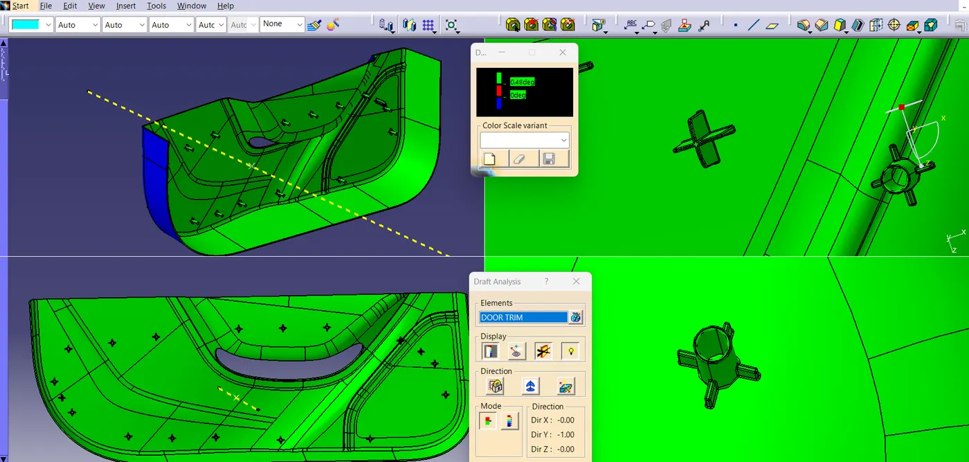
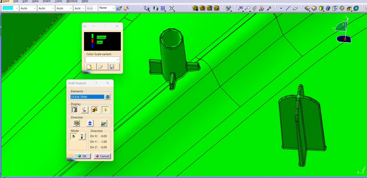
After creating a heat stakes with ribs copied and pasted them special result with link, same followed for 4 way locaters. Totally 16 heat stakes and 2 four way locaters were created as per the reference image and given points.
Screenshots of the completed design in various orientations (Isometric, Front, Side, and Top View):-