Week 10 - Challenge 3 - Door Trim Lower with Engineering Features
Here is a detailed report of the process:
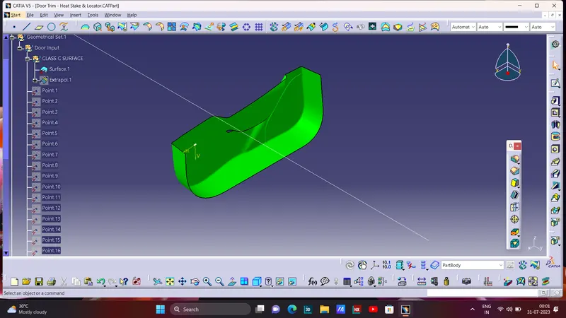
The tooling axis was created by extracting a surface from the Class-A surface and then creating a line through the center of the surface.
The offset surface was created by offsetting the Class-A surface by 2.5 mm.
The gaps in the offset surface were closed by using the patch command.
The Class B surface was created by joining the closed patches together.
The closed body was created by sweeping the boundary of the Class A surface to trim with the Class B surface.
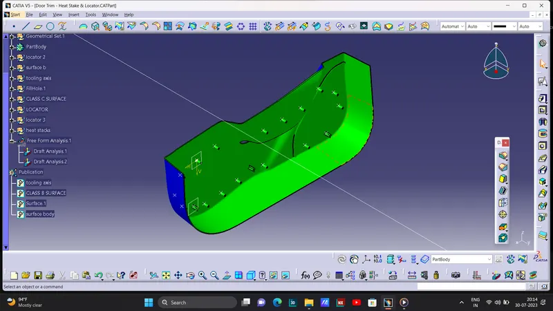
The draft analysis was performed on the closed body, and the minimum draft angle was found to be 3 degrees.
The heat stakes were created by drawing a sketch on the surface and then extruding the sketch to a length of 20 mm.
The locators were created by drawing a sketch on the surface and then extruding the sketch to a length of 20 mm.
The heat stakes and locators were spaced at least 10 mm apart, and they were located in areas with a minimum draft angle of 0.5 degrees.
Draft Analysis:
Draft analysis is a crucial step in plastic component design to ensure proper moldability and release of the part from the mold. It involves determining the angles or tapers on the part's surfaces to facilitate easy ejection from the mold.
Tooling Axis Creation:
The tooling axis is an essential element in the design of molds for plastic components. It defines the direction along which the mold opens or separates to release the part. The tooling axis is crucial for achieving optimal part quality and minimizing manufacturing challenges.
Bisecting Method in CATIA for Tooling Axis Creation
Step 1: Import the Bumper component into CATIA.
Step 2: Identify the reference points, reference lines, and reference planes required to define the tooling axis.
Step 3: Create the reference point(s) using the appropriate CATIA tools, such as "Point" or "Datum Point." Ensure that the reference point(s) are placed strategically on the component to establish the desired axis direction.
Step 4: Construct the reference line(s) using the "Line" tool in CATIA. These lines will serve as guides for the tooling axis direction. Align the reference lines according to the design requirements.
Step 5: Generate the reference plane(s) using the "Plane" tool in CATIA. These planes will define the initial orientation of the tooling axis. Ensure that the reference planes align with the reference lines and are appropriately positioned.
Step 6: Utilize the bisecting line concept to establish the final tooling axis direction. Identify the two reference lines that define the desired axis direction. Construct a bisecting line between these reference lines using the "Bisecting Line" or "Line Bisector" tool in CATIA.
Step 7: Validate and refine the tooling axis placement by analyzing the draft angles and performing simulations or tests if necessary.
Door Trim Lower Plastic component:
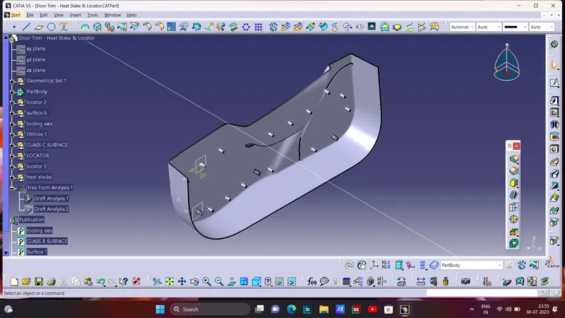
top view:
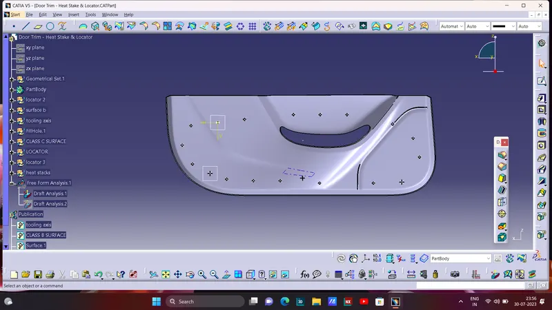
front view:
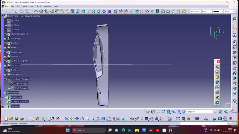
DRAFT ANALYSIS ON FINAL COMPONENT:
DRAFT ANALYSIS ON CLASS A SURFACE: