Week 10 - Challenge 3 - Door Trim Lower with Engineering Features
Respected Sir, as per best of my knowledge from the given videos and with the help of technical team, I completed my challenge. For more details, please look into the below mentioned attachments.
REPORT WRITING ON DOOR TRIM, HEAT STAKES & LOCATORS BASED ON DRAFT ANALYSIS
Initially, the given surface model door trim is seen in 3 different directions such as x, y, and z axis, using compass. This is done to select appropriate axes which cover the entire surface of door trim. Thus, an appropriate axis is selected to create draft analysis. Before doing drafting analysis, the important thing is to create a dummy tooling axis to find the main tooling axis. In simpler surface models, we selected the flat surfaces or flat surfaces consisting holes in a rectangular planes to create the main tooling axis. As we know that, door trim is a type of complicated unique shape. Hence, entire surface model is selected directly to do the drafting analysis by creating the dummy tooling axis as the main tooling axis.
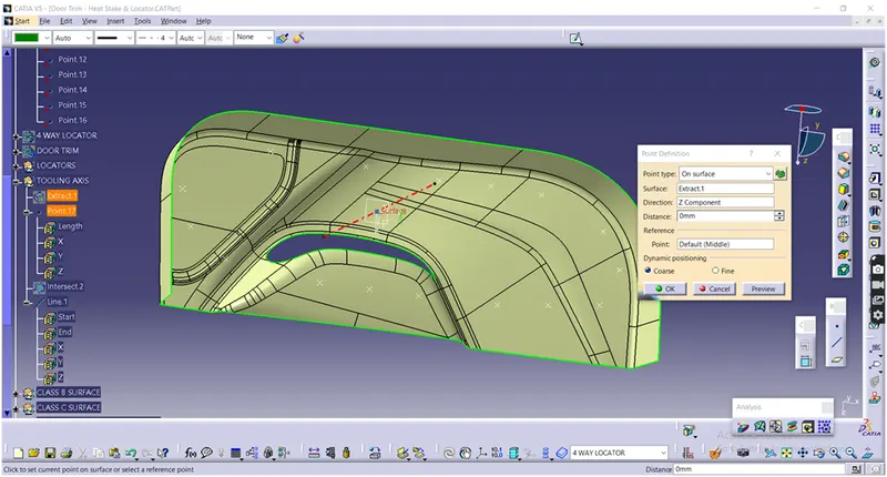
By using intersection command, an appropriate plane and class A surface is selected. Now the sketch is generated, through which draft lines has to be selected. With the help of line command and point generated on the flat surface, directly an actual tooling axis has drawn. Now, this tooling axis which is generated will help us to create a class C surface using sweep command in future or further processing.
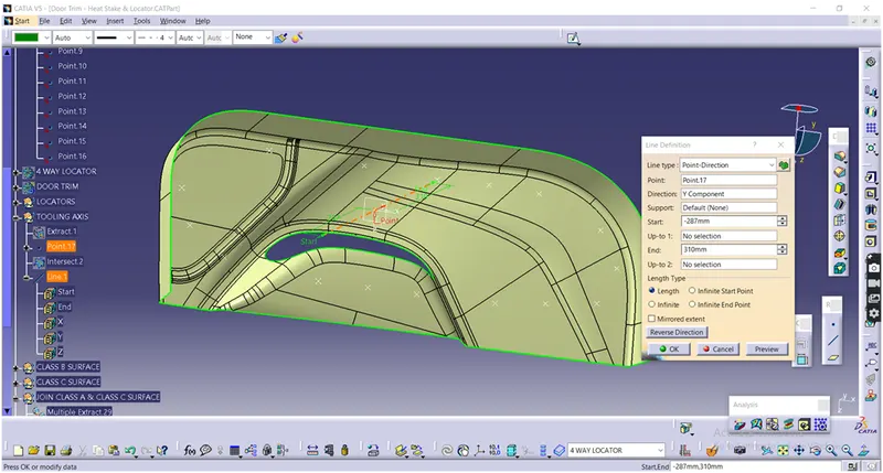
Similarly, another image is represented above as Fig (b), which depicts the line drawn through the point created using the line command, by selecting point-direction option. This line drawn is nothing but, it acts as a dummy tooling axis. Due to complicated surface model, this dummy tooling axis is referred as main tooling axis and done draft analysis further.
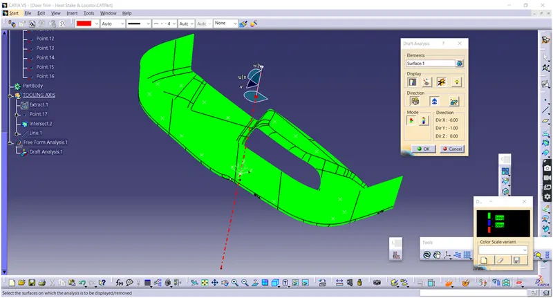
Figure mentioned above shows draft analysis performed on class A surface with 3 degree draft after creating the main tooling axis. During draft analysis, initially the compass have brought and coincided with main tooling axis. Now, once again the compass option have clicked and moved from the main tooling axis and once again coincided with the same axis. So that the given class A surface is turned into green colour by clicking the mouse pointer on the surface and selecting the inverse draft option. Now, here at 3 degrees, portion of the surface is successfully turned into green.
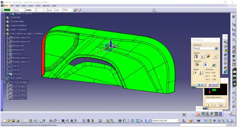
Above figure depicts that, once again draft analysis performed on closed surface after final trim of class A, B & C with 3 degree of draft. Draft analysis is done same as draft analysis made on class A surface when main tooling axis is created.
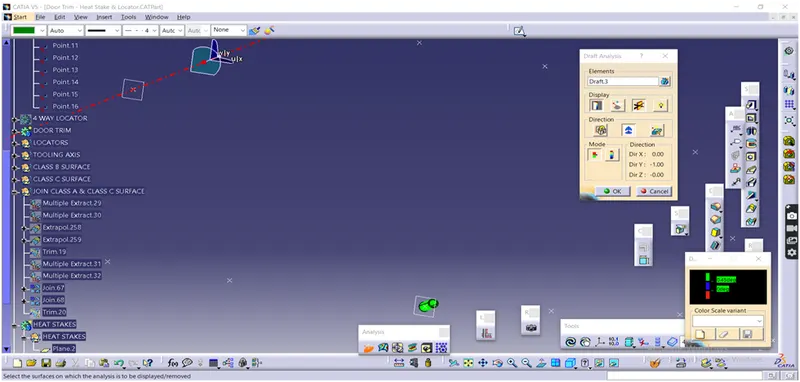
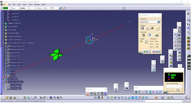
The above two figures mentioned, depicts that draft analysis made on locator and heat stake, as the draft analysis have done here at 0.45 degrees as per design rules with respect to main tooling axis. Here for locator inside face and outside faces the draft angle is given about 0.5 degrees.
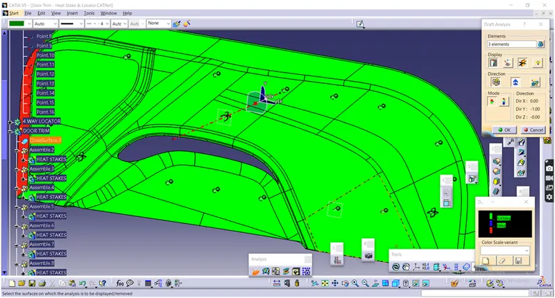
Finally, after translation of heat stakes, draft analysis is made on door trim, heat stakes and 4 way locators, with an angle of 0.45 degrees draft, and observed that the surface on which locators and heat stakes mounted on given points and surface is successfully turned into green. Here also draft analysis is performed same like the draft analysis performed for class A surface, except that final closed surface assembled with heat stakes and locators, door trim were performed draft analysis at 0.45 degrees instead of 3 degree draft.