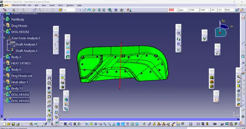
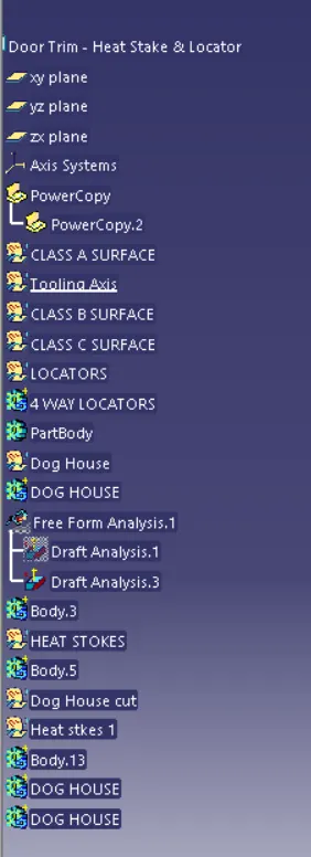
Week 10 - Challenge 3 - Door Trim Lower with Engineering Features
Title: Solid Body Creation and Draft Analysis of Door Trim Lower using CATIA V5
CLASS A Surface
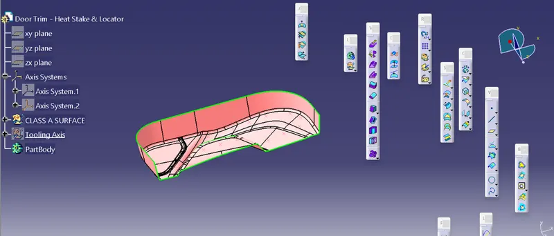
Tooling Axis
Tooling axis is a direction in which core and cavity opens and closes. Draft angle is provided with respect to the tooling axis.
Tooling Axis created using Bisecting Method
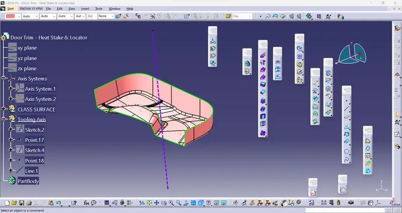
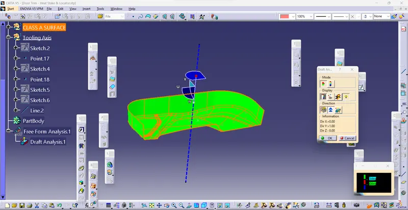
DRAFT ANALYSIS OF CLASS A SURFACE
Green colour - above 3 degree positive draft
Red colour -between 3 and 0
blue colour- below 0 degree
View changed to material mode
CLASS B SURFACE
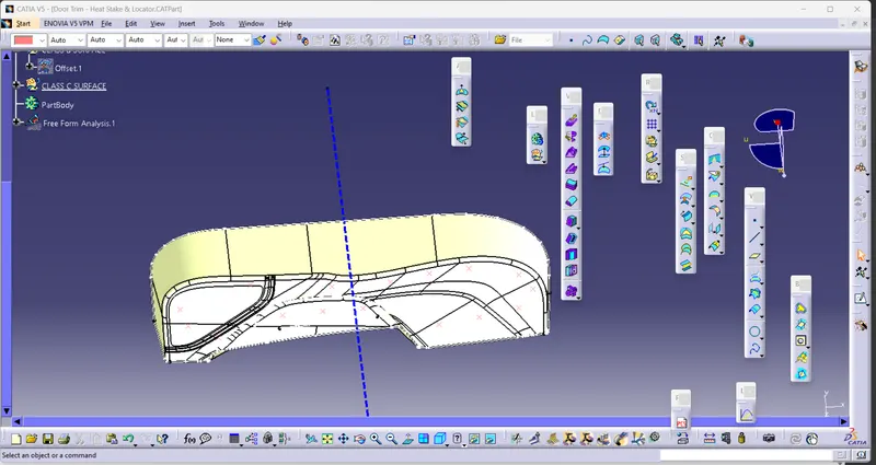
B SURFACE is created by Offseting the class-A surface to 2.5mm inward direction.
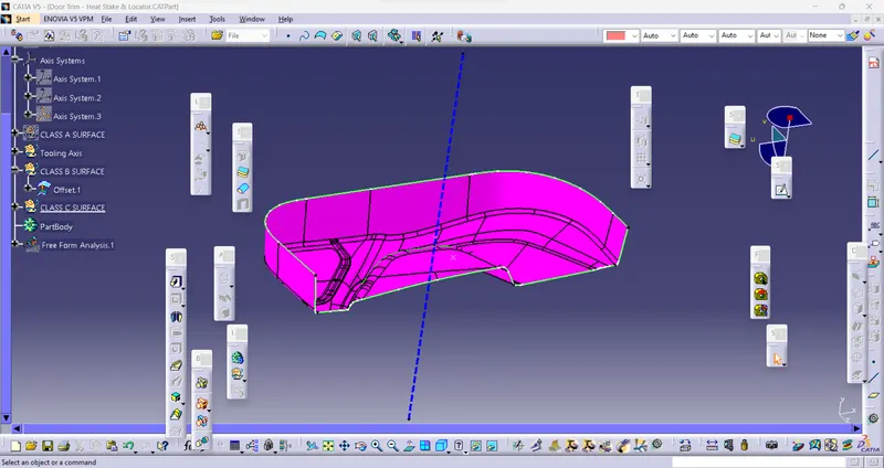
The surface that joins class-A and class-B surfaces are class-C surfaces.
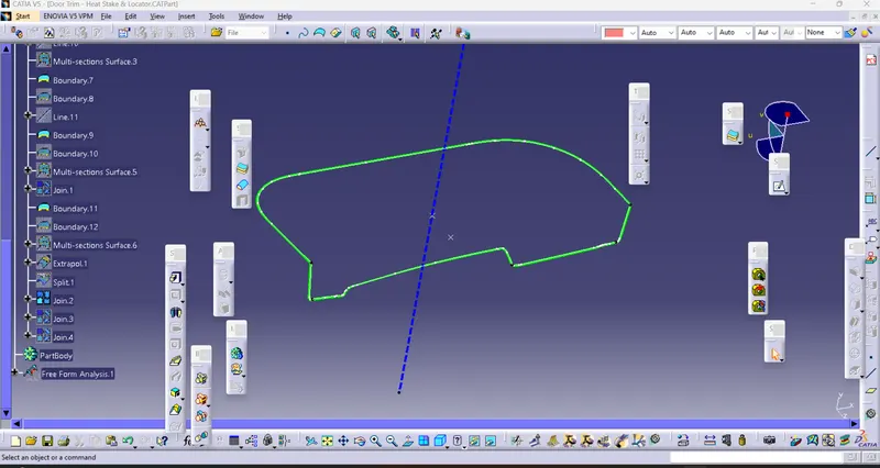
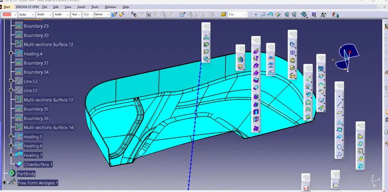
Closed Body:
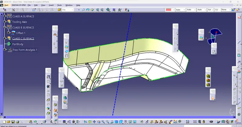
PART BODY:
To create the solid part body from the closed surface, I used the closed surface command in the part workbench.
CREATION OF LOCATORS and HEAT STAKES:
In the process of fabricating the locators, I initiated by sketching the desired design on the designated body. Subsequently, I applied a padding operation, resulting in a 20mm height extension, followed by a thickness of 1.3mm. Additionally, I incorporated a 0.5-degree draft aligned with the tooling axis to ensure optimal manufacturability. To further enhance the functionality and precision of the locators, I applied a 5mm chamfer with a 45-degree inclination, enabling improved alignment and stability. Finally, I introduced a fillet with a radius of 0.25mm, providing a smooth transition and diminishing any sharp edges.
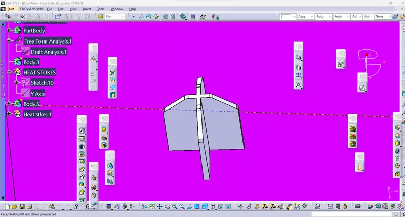
To create the heat stakes, I begin by creating a precise sketch on the desired surface. Subsequently, I apply a 20mm height padding to the sketch, while also incorporating a draft angle of 0.5 degrees on both the inner and outer sides. Additionally, I introduce a 0.25mm radius fillet to ensure smoother transitions. Once the heat stakes are created, I proceed to design supportive ribs. For this purpose, I draw another sketch and apply a20 mm height padding with a thickness of 1mm. Following the padding, I implement a 0.5-degree draft in the direction of the tooling axis and introduce a 0.25mm radius fillet to enhance structural integrity. Finally, I employ a union trim operation to eliminate any ribs encroaching into the heat stakes, thereby achieving the desired configuration.
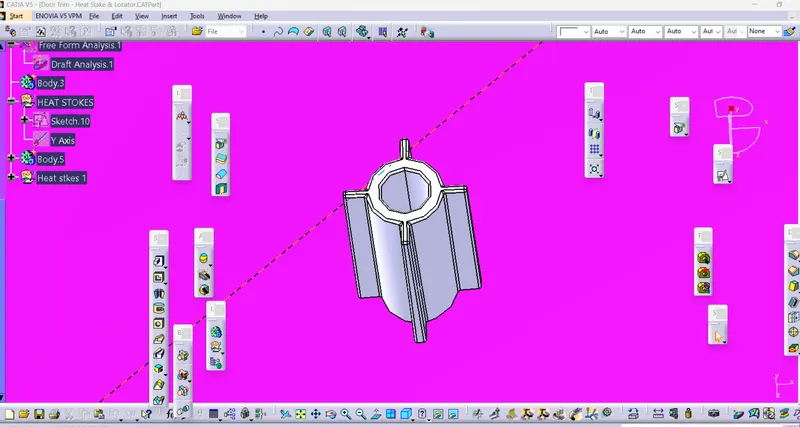
Now I Power copy the heat stakes by giving inputs like point and plane copy them in the part body according to the requirement.
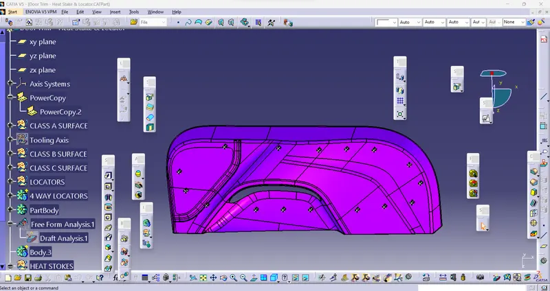
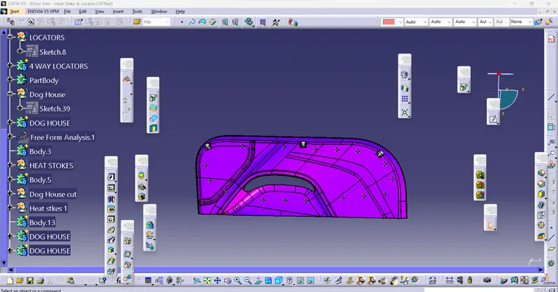
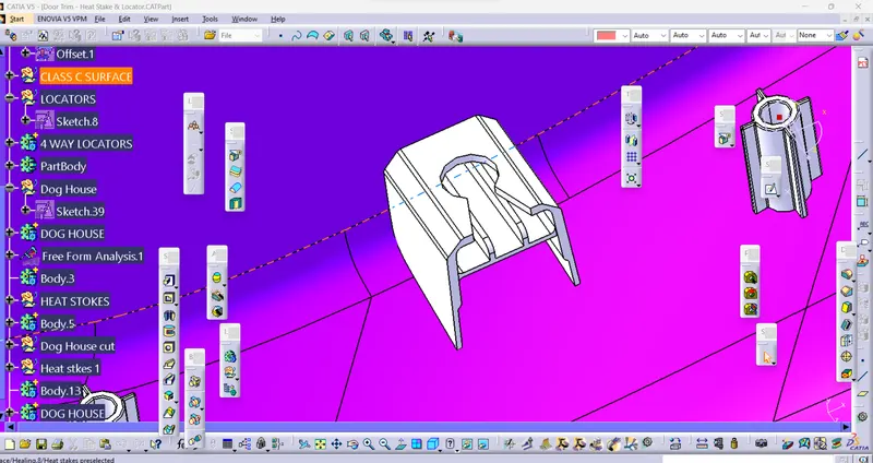
CREATION OF DOG HOUSE:
Dog house is an engineering feature used in plastic trim design. Dog houses are used as supporting feature. Sometimes other engineering features like snaps; locators etc. are mounded on them to increase their strength.
DRAFT ANALYSIS FOR PART BODY: