Week 10 - Challenge 3 - Door Trim Lower with Engineering Features
Week 10 - Challenge 3 - Door Trim Lower with Engineering Features
Ojective :-
Create the Door Trim Lower Plastic component through the given Class-A surface. To begin with, the tooling axis for the given Class-A Surface should be created meeting the requirements of the draft angle and at the end perform the Draft analysis on the model.
Create the Heat Stakes and the locators considering the design rules mentioned in the video for the door applique.
Tooling Axis Creation
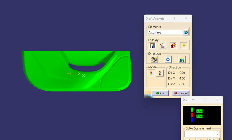
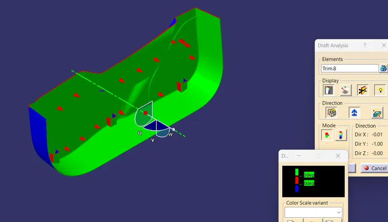
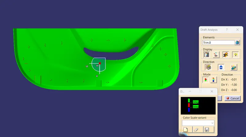
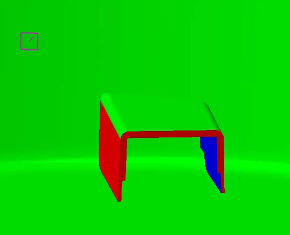
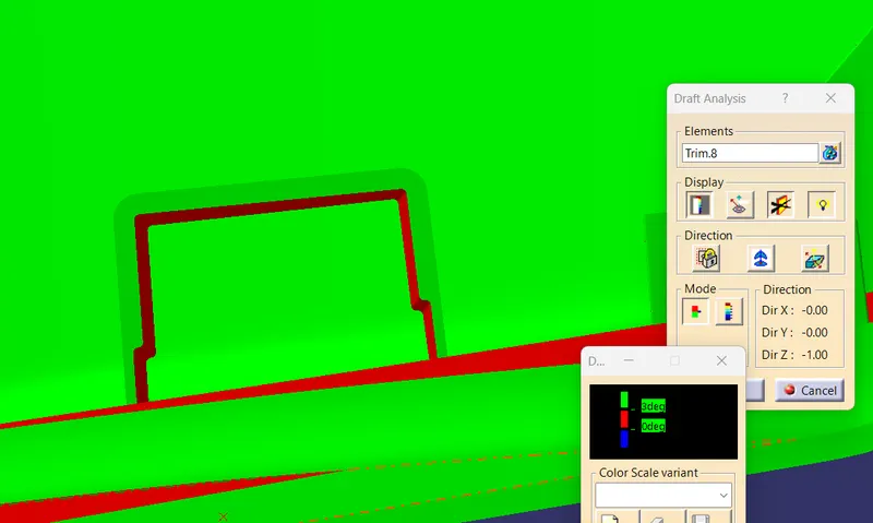
To create the tooling axis, I extracted a surface from class A and created a point in the middle of the surface by using the point command and created a line at that point through the x-axis. Now, I performed a draft analysis check from that line whether the created tooling axis is in the correct position or not. If in the draft, analysis check the surface highlighted with green colour on both sides of the surface the tooling axis is in the correct position and direction.
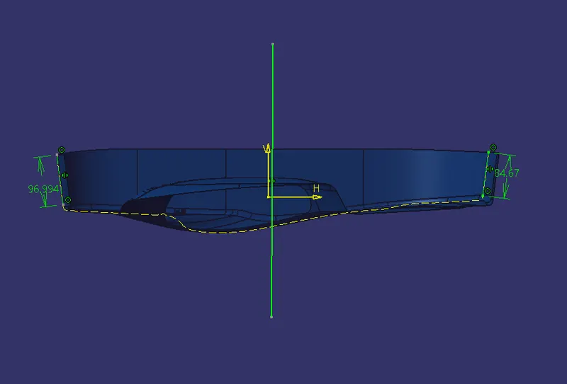
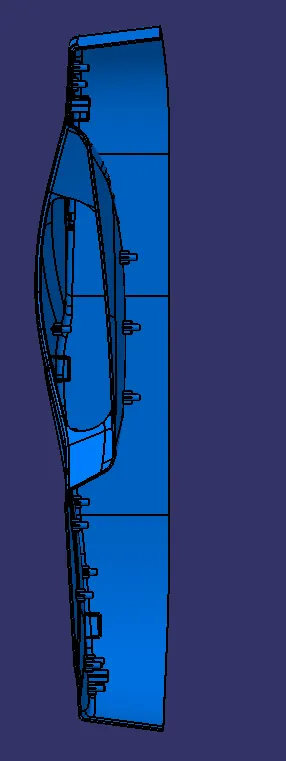
The Given A Surface And Draft Analyis
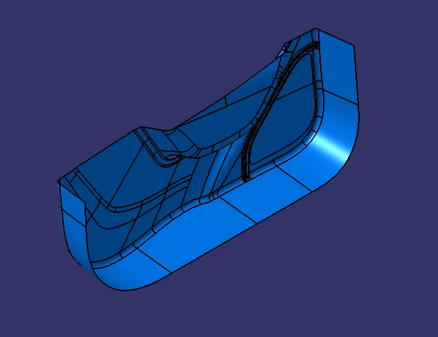
Isometric View
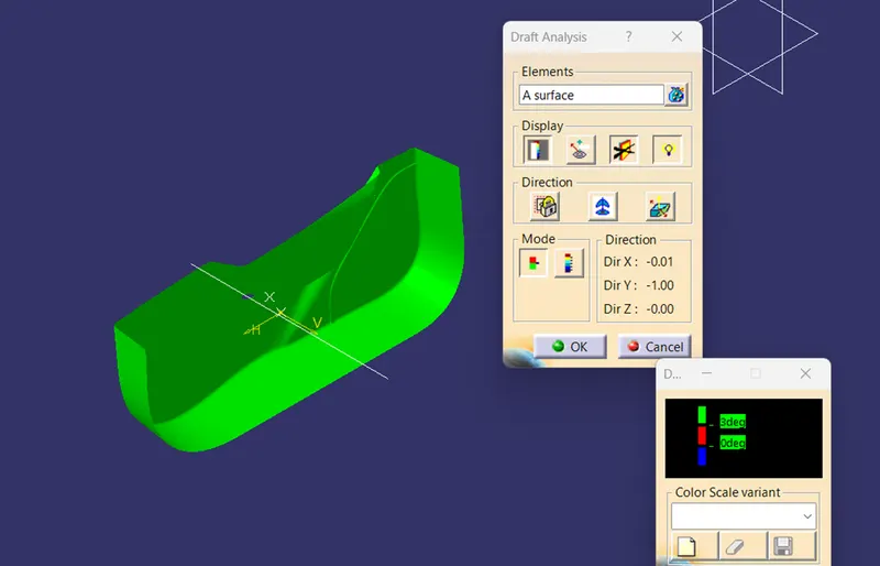
Front View
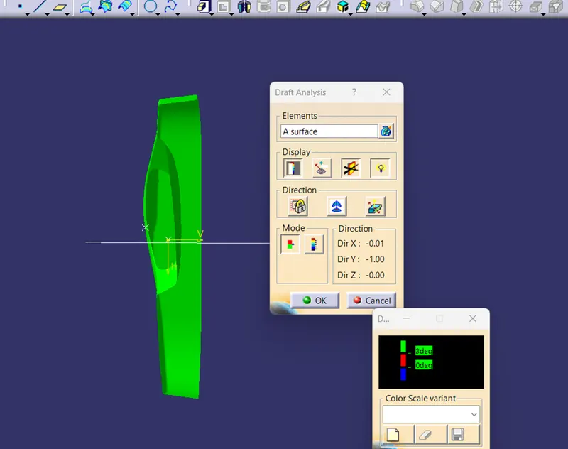
Side View
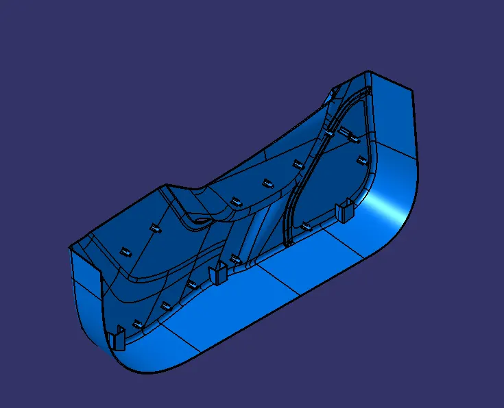
Solid Body various orientations
Isometric View
Front View
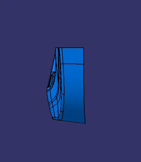
Side View
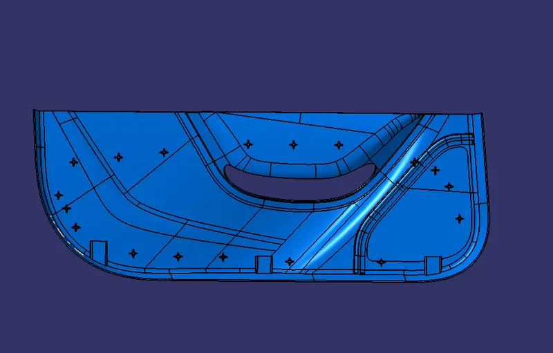
Top View
Draft Analysis For Solid Body
Heat Stack Making
Inner Dia =5mm
Outer Dia =7mm
Draft =0.5mm
Radius =0.25mm
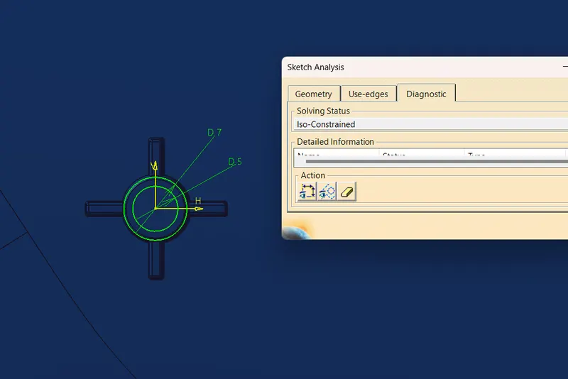
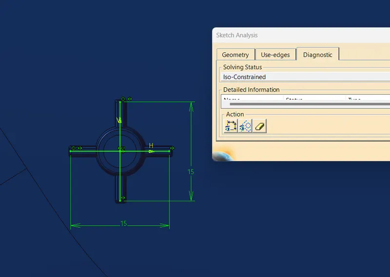
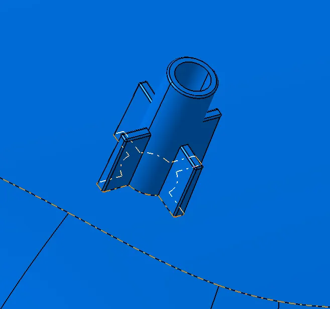
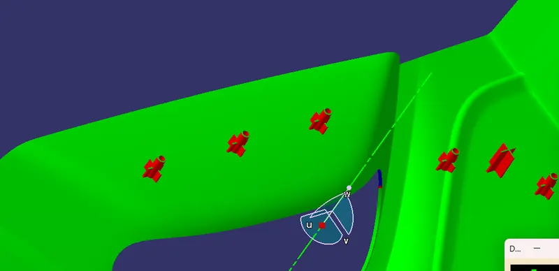
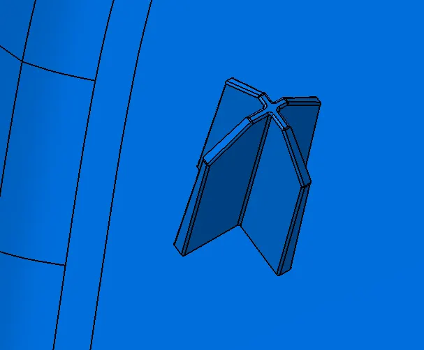
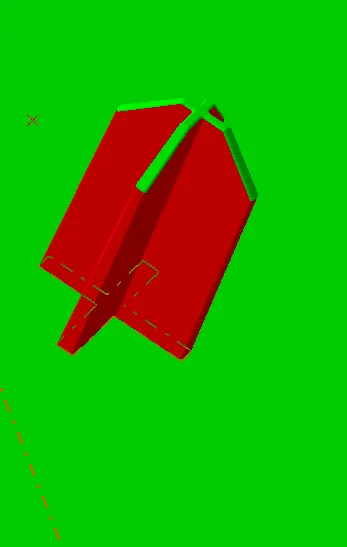
4 Way Locator
- Make sketch for the loactor and pad it
- Give draft about minimum 0.5mm
- Minium radius = 0.25
- Chamfer = 5*45°
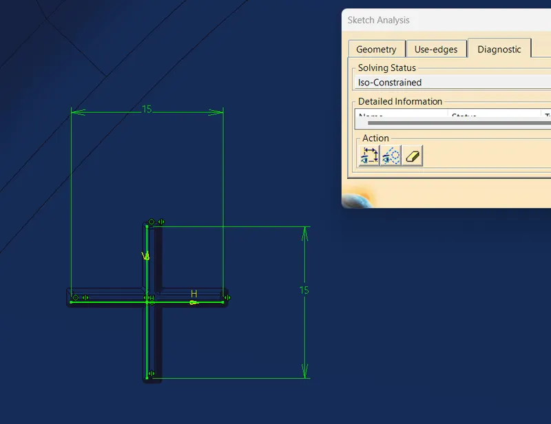
Dog House
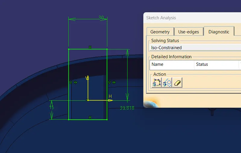
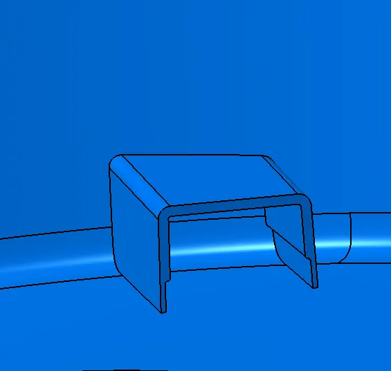
The core Height should be 3mm to 6mm
minimum draft Given is 1.5mm
Curing thickness 40% of the part thickness =2.5*0.4=1mm
Conclusion :
Hence, the Door Trim Engineering Features was created by considering the design rules, and the Draft analysis performed on the final component is successfully done