Week 10 - Challenge 3 - Door Trim Lower with Engineering Features
REPORT :
- Aim : To create a Door Applique Plastic Component through a given Class A Surface and perform Draft Analysis on the final plastic component.
-
Objectives :
- Creation of Tooling Axis.
- Creation of Class B and Class C surface.
- Creating a solid part out of surface modelling.
- Draft Analysis of Class A surface and final plastic component.
- Introduction : In this project we are designing a Door Applique using given Class A surface. The approach includes creation of Class B surface keeping 2.5 mm thickness in mind for the complete component. The design also included Class C creation from the given parent surface.
Constraints :
- NO CHANGES IN CLASS A ARE ALLOWED (BUT CLASS A & CLASS C SURFACE JOIN CREATE OPEN BOUNDARY, SO I HAVE TO EXLAPORATE CLASS A & TRIM WITH CLASS C).
- ALL DESIGN RULES SHOULD BE STRICTLY FOLLOWED.
- ALL SURFACES SHOULD BE CLOSED BEFORE CONVERTING TO SOLID.
- ALL FACES SHOULD MEET THE ALLOWED DRAFT REQUIREMENTS.
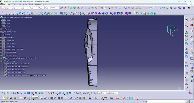
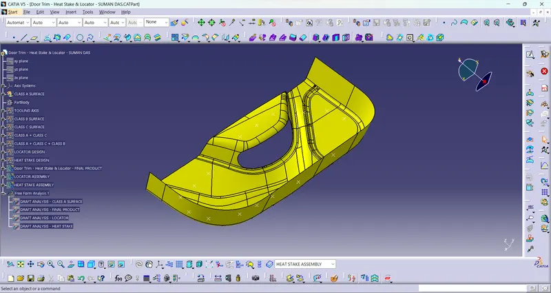
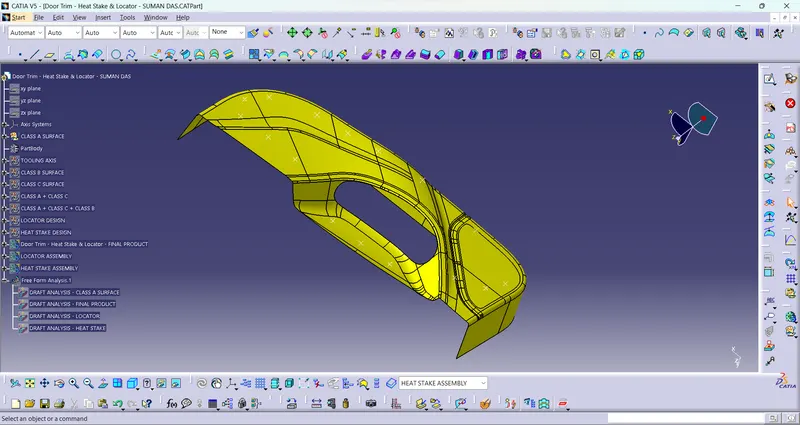
CLASS A : Following surface is given as the input for the component creation.
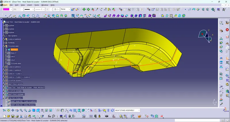
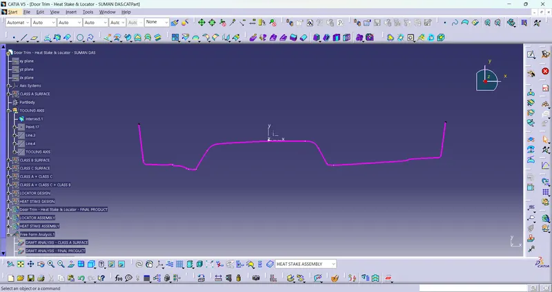
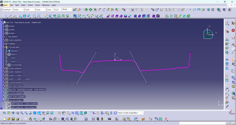
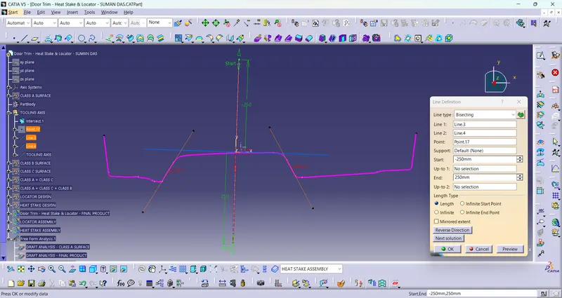
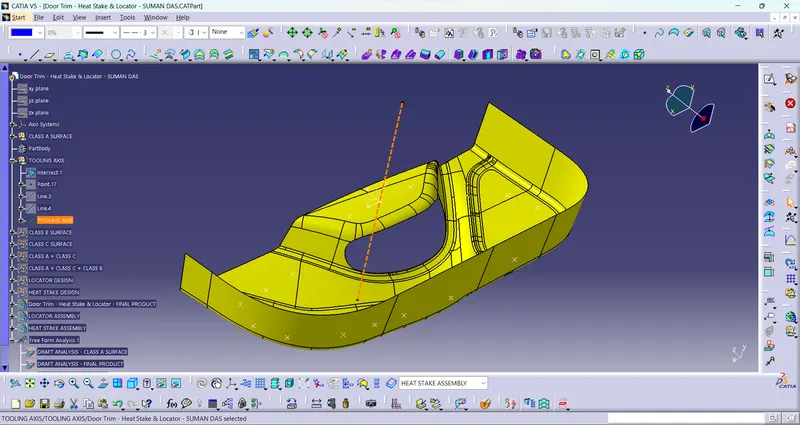
- Creation of Tooling Axis : Create an intersection of CLASS A surface with XY plane and from the intersection create the tooling axis as shown below. We should keenly observe and study the Class A surface to create the 'Tooling Axis' for the component, for the above-given Y-axis is the best suitable tooling axis.
-
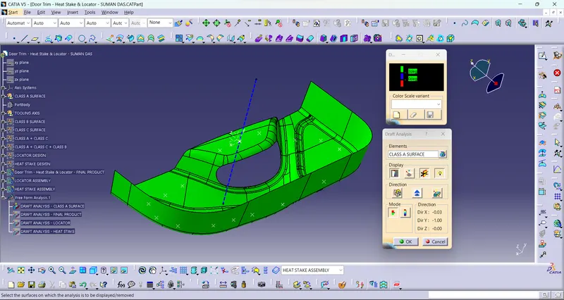
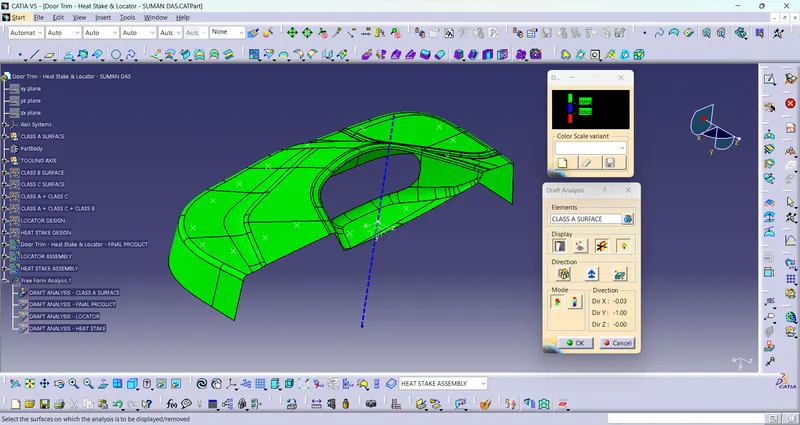
Draft Analysis for Surface A :
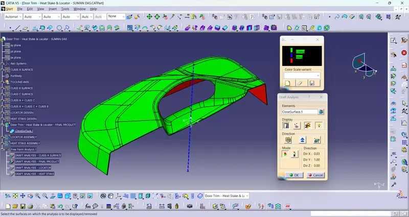
The analysis is done for 3degree draft. So as can be seen all the surfaces are more than 3deg.
-
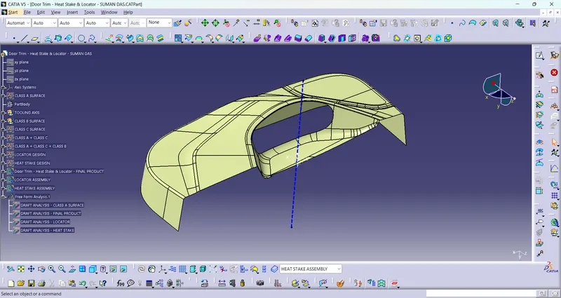
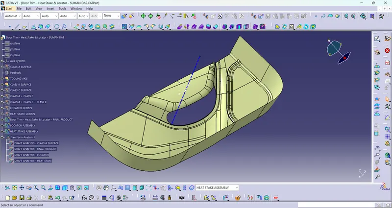
Creation of Class B :
- Now for Class B creation, we have extracted surface from Class A and untrimmed them to obtain the original parent surface.
- These surfaces are then offset to the required thickness.
- After offsetting, all the surfaces are trimmed into the required shape.
- Required fillets are given to the surfaces.
-
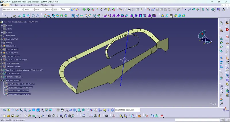
Creation of Class C surface :
- For creating this surface we have extracted the boundry of Class A using multi-extract and then converted to smooth curve.
- Now this smooth curve is swept along the draft direction with a 3deg draft.
-
Final Product :
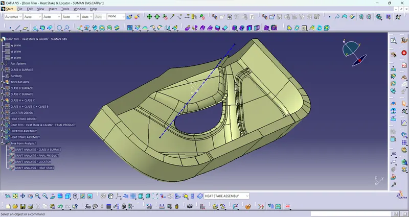
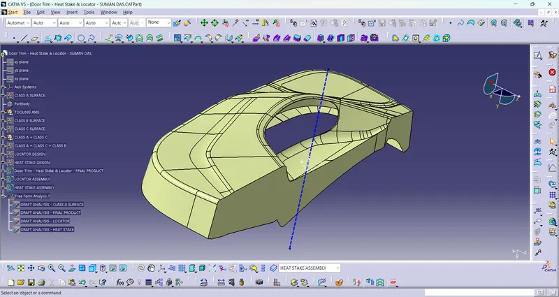
Class A + Class C :
To make sure that there is not any open boundry between class A and class C, we have used join option to created the single body. This is done to make sure that the parting line doesn't lie between the these two surfaces.
-
Class A + Class B + Class C :
For this we have trimmed the above shown surface with the Class B surface using trim feature.
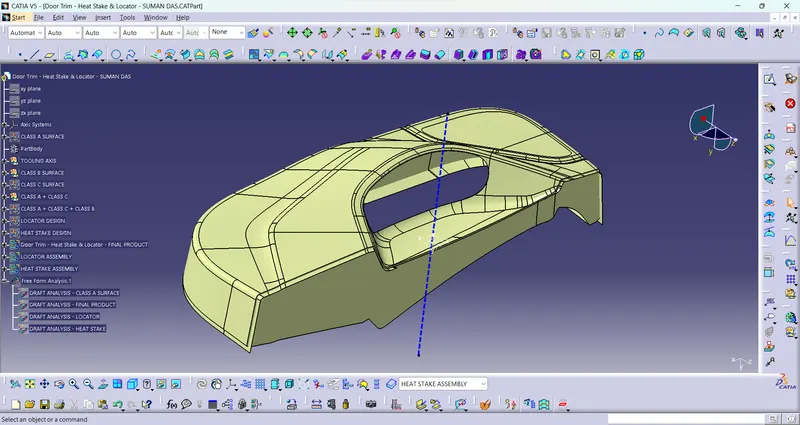
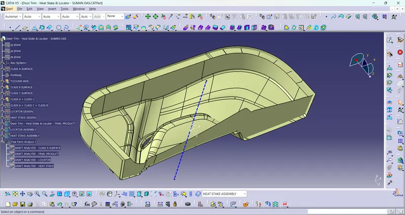
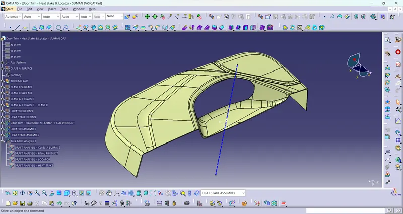
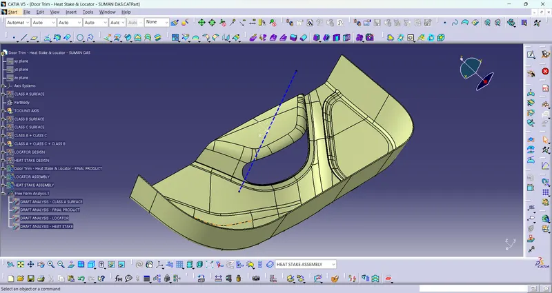
All the main features are published as can be seen in the image shown above.
- Close Surface : We perform a close surface operaration to ensure that there is no open boundary of the final product of the Door Applique.
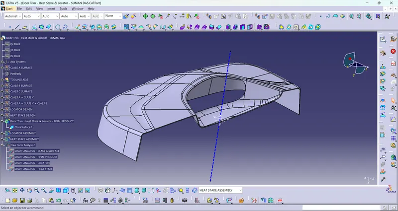
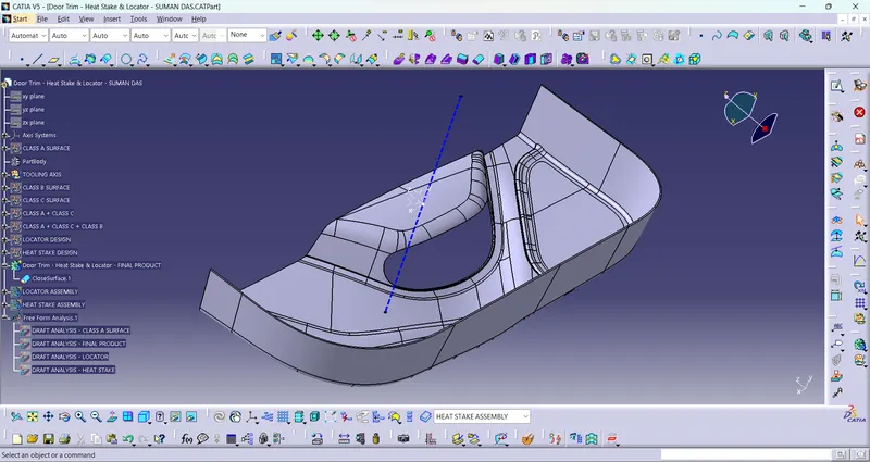
-
Draft Analysis on the Final Component : For this analysis, main tooling axis is taken draft reference. Following results were obtained.
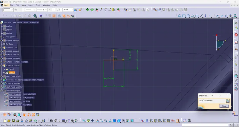
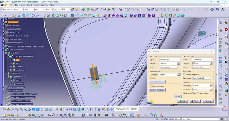
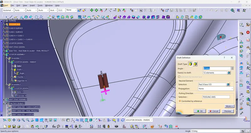
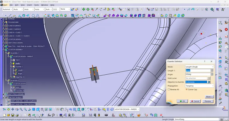
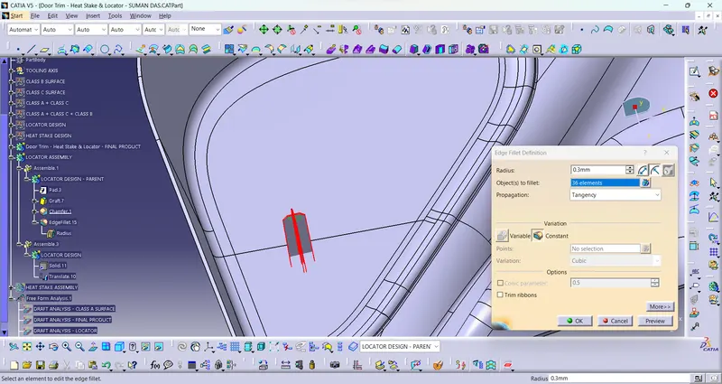
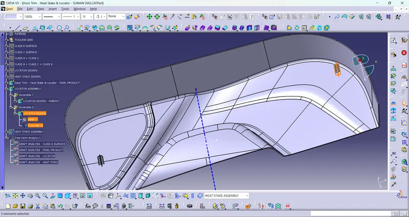
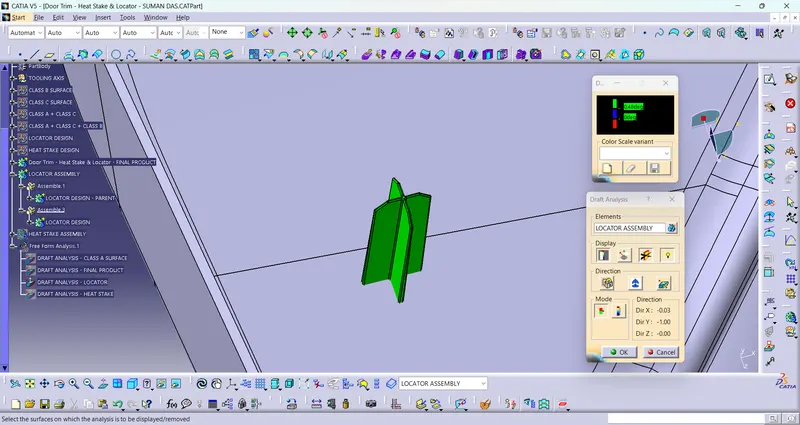
- LOCATOR DESIGN : First I sketch two 15mm cross-line. Then I pad the lines with neutral fiber option giving the length of 40mm. Then I draft the pad with 0.5 degree. Then I give the pad 3mm & 45 degree chamfer. Then I fillet all the edges with R=0.3mm. Then copy it & do paste special operation. Then I translate the Parent-Locator to another specific position. Then I assemble 2 Locators in a single body. Then I do the Draft Analysis with main tooling axis taken as draft reference & following results were obtained.
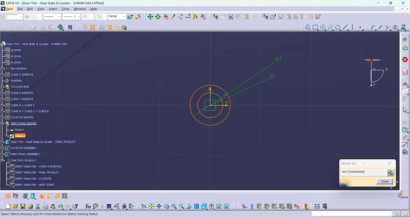
- HEAT STAKE DESIGN : First I sketch 2 circles having D=8mm & D=5mm with same centre. Then I pad the circles giving the length of 30mm. Then I draft the pad with 0.5 degree. Then I fillet all the edges with R=0.25mm. Then copy it & do paste special operation. Then I translate the Parent-Heat Staker to another specific positions. Then I assemble 14 Heat Stakes in a single body. Then I do the Draft Analysis with main tooling axis taken as draft reference & following results were obtained.
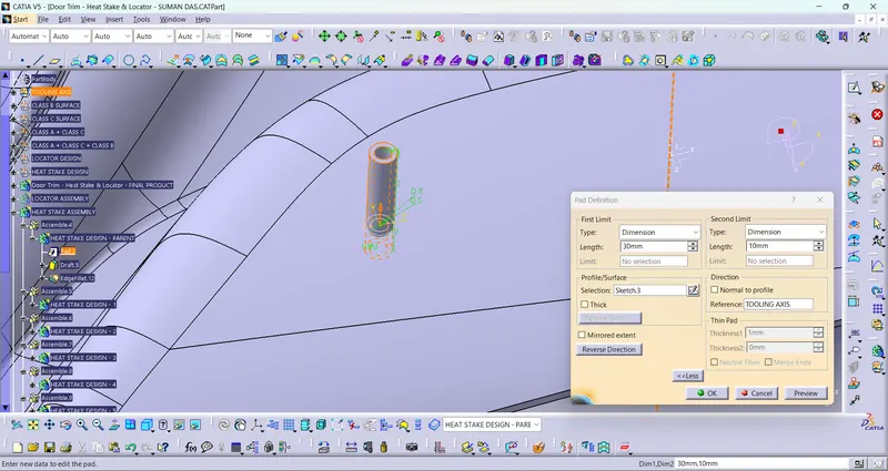
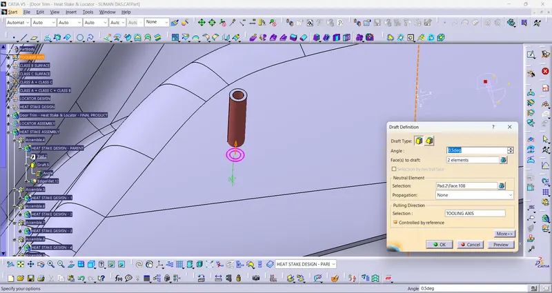
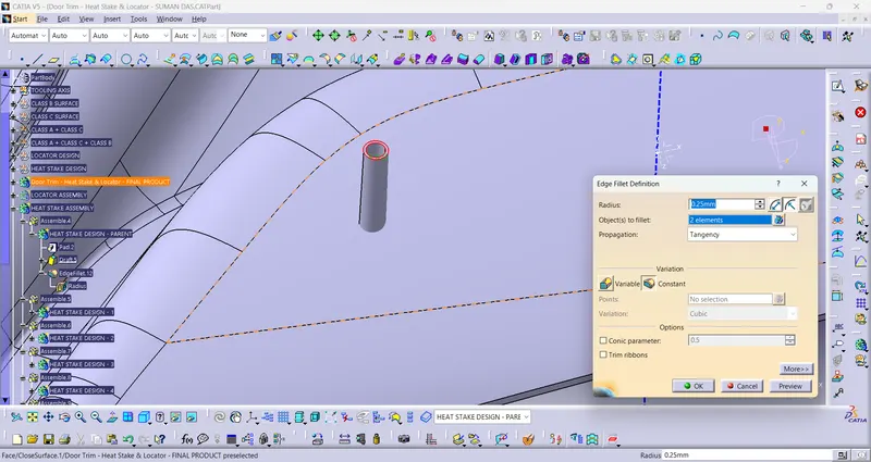
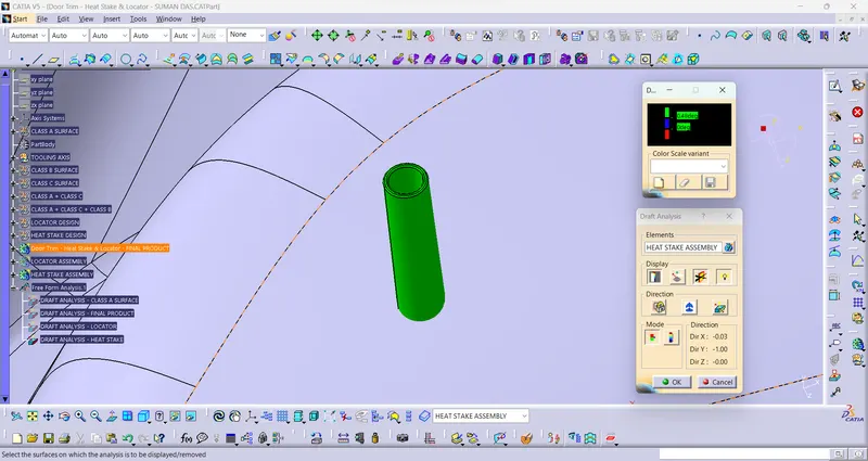
Then I do the union trim operation of all the Locators & Heat Stakes with the main body.
- Draft Analysis on the Final Component with Locators & Heat Stakes : For this analysis, main tooling axis is taken draft reference. Following results were obtained.
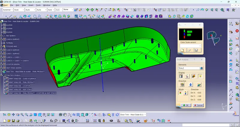
- ISOMETRIC VIEW :
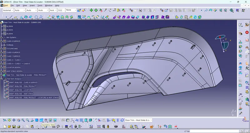
- FRONT VIEW :
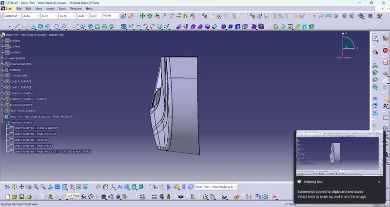
- SIDE VIEW :
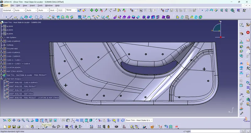
- TOP VIEW :