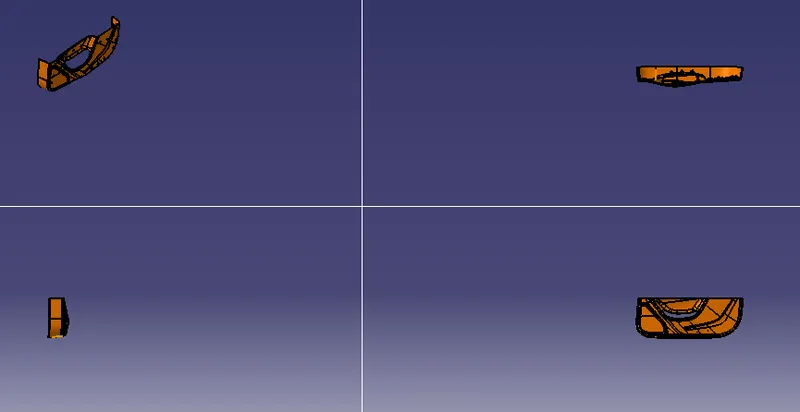
Week 10 - Challenge 3 - Door Trim Lower with Engineering Features
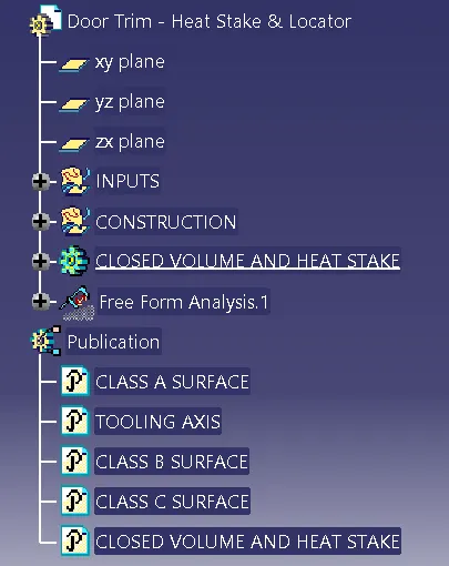
TREE STRUCTURE:
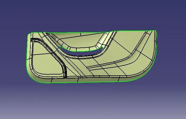
CLASS A SURFACE:
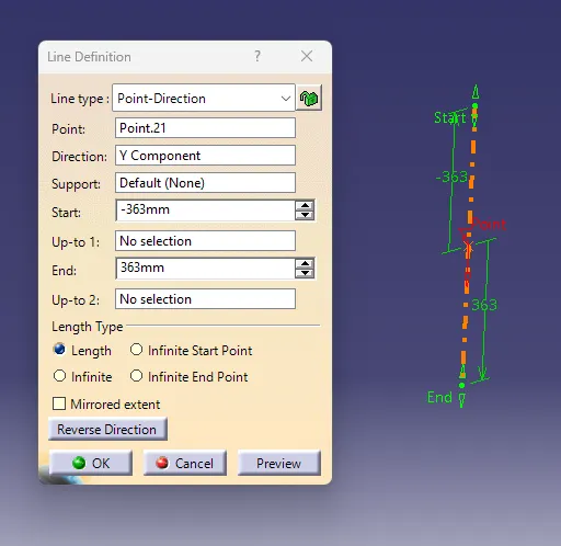
TOOLING AXIS:
Check the best possible tooling direction by manually adjusting the compass.By analysing it is found thathe t y axis as tooling direction would clear most of the faces without any difficulties.Now extract any surface and create a mid-point on it.Then create a dummy axis creating a line on the point and direction along the y-axis.Perform draft analysis to find whether the given axis clears the draft analysis. If not create a new tooling axis.
DRAFT ANALYSIS(CLASS A SURFACE):
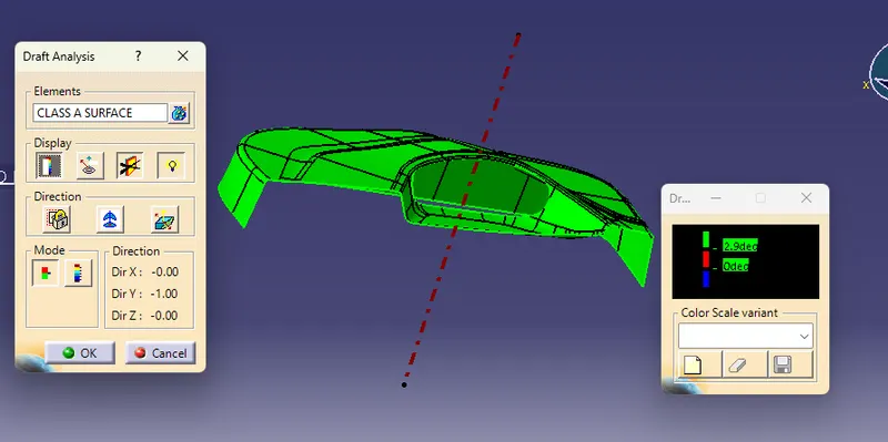
Now perform the Draft analysis using the Featured Draft Analysis tool in the tools.Then after opening the draft analysis tool box ,go for the compass and place the compass alinged to tooling axis, and click on the lock symbol to lock the position. after alinging click on the surface which we want to do draft analysis,minimum draft angle given is 3 degree.it shows green colour once its finished.
CLASS B SURFACE CREATIONS:
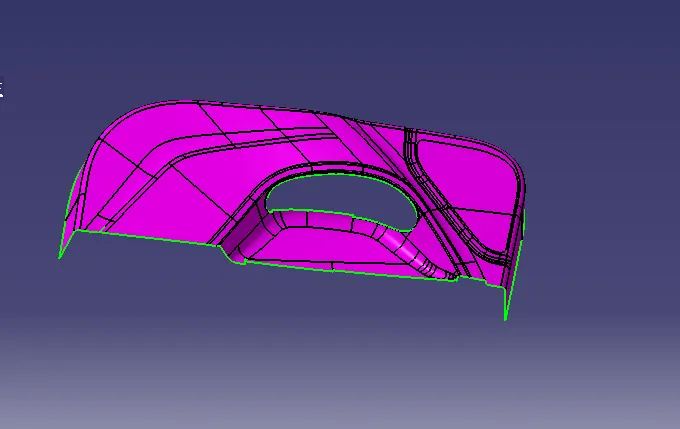
Class-B surface means the thickness of a part it is not visible and is inside part. In other words, the Class-B surface is a surface below a certain thickness from the class-A surface. This is the surface that contains engineering aspects of a model.Create an offset surface of Cin LASS-A about 2.5mm inward direction.Check for discontinuity and rework on the offset surface using extract, multi-extract, multi sections surfaces.Join the surfaces and ensure the final CLASS-B surface created has no gaps.
CLASS C SURFACE:
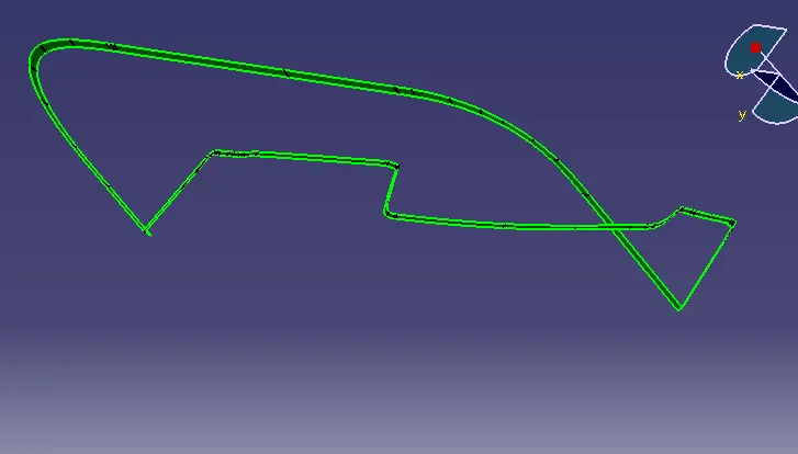
The surface that joins class-A and class-B surfaarethe s is class-C surface. Class C is often specified for interior surfaces not readily visible, surfaces that will be covered by another part when assembledCreate the sweep concerningerence to the surface and tooling axismulti-extractingting the CLASS-A boundaryJoin the sweep surfaces by using commands like extrapolate, trmulti-sectiontion surface.Finally join all the sweep surfaces and ensure the continuity of the CLASS-C surface.
FINAL SURFACE:
For creating the Finals door trim surface, join the CLASS-A and CLASS-C surfaces together.Then Extrapolate the B surfacea little bit outward direction to make sure that there would not be any gap when trimming with the joined surface.Then trim the extrapolated CLASS-B surface wthe ith Join surface (CLASS-A and CLASS-C).
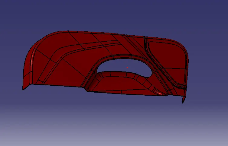
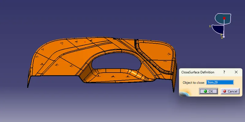
Make a solid part body using the close surface command in the part design workbench
4 WAY LOCATOR:
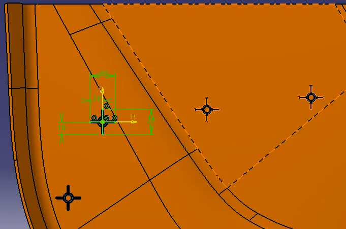
After creating the sketch, pad it to 20mm height and thicken it to 1.3mm and drafted it to an angle of 0.5deg in the direction of the tooling axis.then gave 3mm length chamfer with 45deg of inclination,fillet the edge with 0.25 mm.
HEAT STAKES:
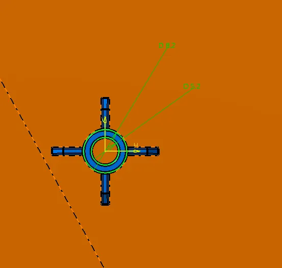
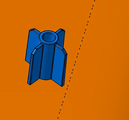
After the creation of the sketch, pad it to 15mm height and give a draft angle of 0.5deg on both sides (inside and outside) and then give a fillet with a 0.25mm radius. After creating the heat stake, create the ribsto heat stake for strengthening purpose. To create the ribs, draw a sketch and padded it to 6mm in height and 1mm in thickness. After padding the ribs, draft to an angle of 0.5deg to the tooling axis direction and fillet to a 0.25mm radius. Then trim the unwanted areas by using union trim with main plastic body.
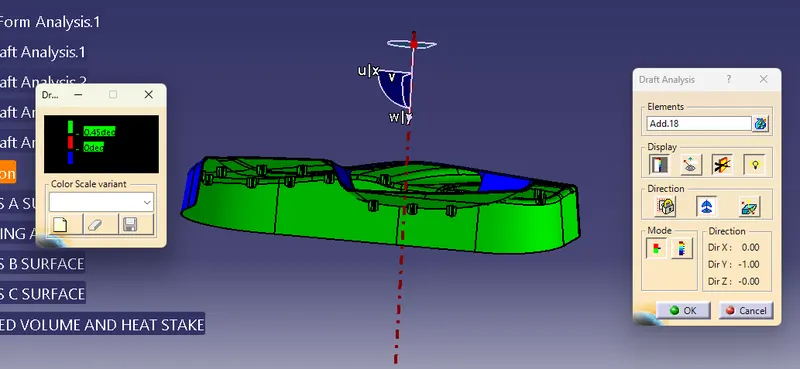
FINAL DRAFT ANALYSIS:
DIFFERENT VIEWS OF PART BODY: