Week 10 - Challenge 3 - Door Trim Lower with Engineering Features
Create the Heat Stakes and the locators considering the design rules mentioned in the video for the door applique.
What is draft: The draft is the amount of taper for moulded or cast parts perpendicular to the parting. line. Draft angles are a design consideration that makes it much easier for a part to release cleanly from a mould. A draft angle is calculated as a degree measurement (or, less often, an inch or millimetre measurement) from the vertical axis of a mould, and it helps account for thermoplastic shrinkage, a practical reality of the injection moulding process for most materials.
Draft angles are generally a requirement of injection moulding design (though there are a select few soft materials, like nylon, that can get away with draft angles of zero). The draft should be a part of the design for manufacture, and all stakeholders and contributors should be aware of its need at the outset of the design process. This includes product designers, design engineers etc and this allows considerations for design requirements to be taken into account. Any draft is always better than no draft.
Why draft is importance:
By accounting for thermoplastic shrinkage during the cooling process, draft angles significantly reduce friction between the finished, cooled part and the side of the mould, Not only does this create a much easier release process, but it also offers several other benefits, depending on the design of the part which is as follows:
Reduces the chance of damage to the part due to friction during the release.
Reduces wear and tear and chances of damage to the mould.
Ensures a uniform, smooth, unscratched finish when required.
Ensures the integrity and uniformity of other surface finishes and textures.
Reduces overall cooling time by lessening or eliminating the need for unconventional ejection setups.
Most, if not all, of these benefits, offer either direct or indirect overall production cost reductions.
STEPS :-
1) Import class A surface
2) Create a tooling axis
3) Draft analysis of class A surface
4) Create class B surface
5) Create class c surface
6) Trim and joint class A,B and C surfaces
7) Create body using close surface
8) Create heat stakes with draft
9) Copy and translate to each point
10) Trim them with main body
11) Create locators and give draft
12) Trim them with main body
13) Draft analysis of final body
Images :-
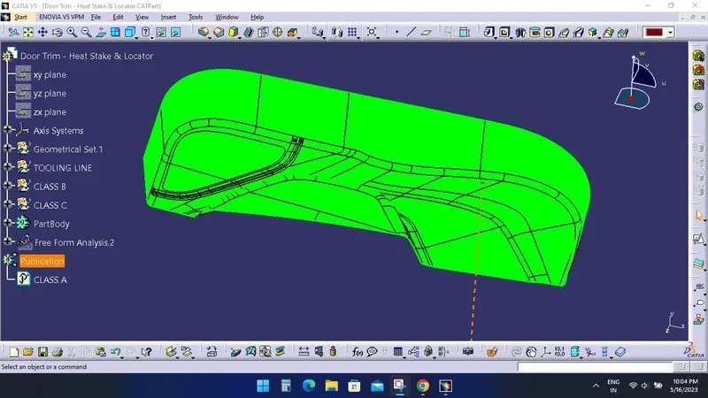
Draft analysis of class A surface :-
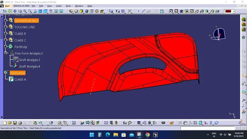
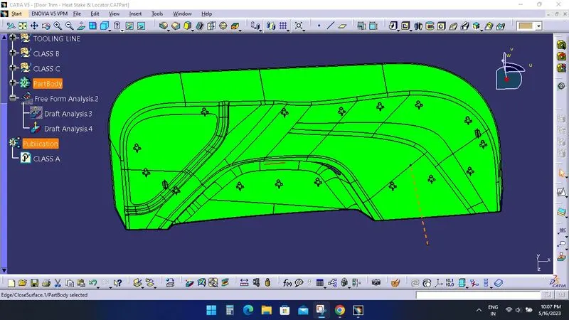
Draft analysis of final body :-
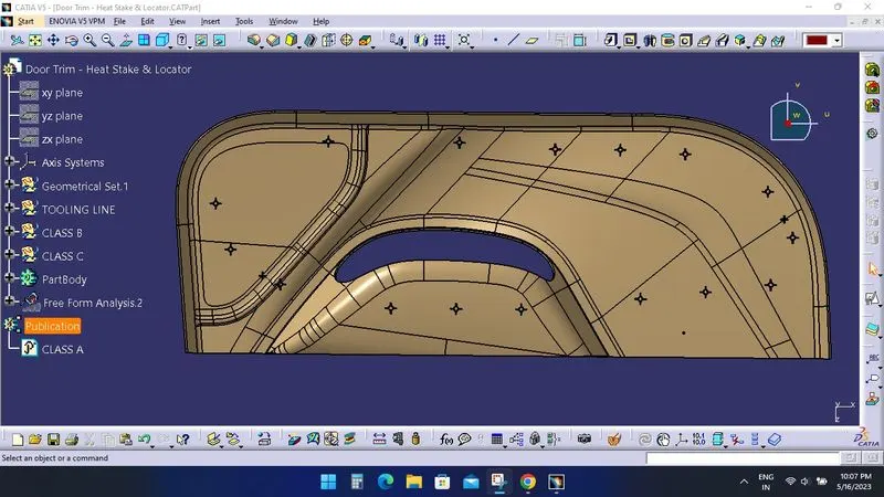
Final body with heat stakes and locators :-
Cad file is attached.