Week 10 - Challenge 3 - Door Trim Lower with Engineering Features
Heat Stake:-
Heat staking also known as thermoplastic staking is the process of joining two dissimilar materials together. In heat staking we use local heating and cooling to raise the temperature of plastic components and allow plastic reforming to be carried out. This reforming can be used in a wide variety of applications.
Applications range from staking plastic bosses for assembly of car door panels to joining PCB’s to plastic housings. Benefits of this technique include; no vibration damage, no particulates, the ability to stake metalized coated applications and the capability to stake in difficult to access or restricted areas.
Locators:-
Locators provide a positive stop for the workpiece. Placed against the stop, the workpiece cannot move. Clamps, on the other hand, rely only upon friction between the clamp and the clamped surface to hold the workpiece. Sufficient force could move the workpiece.
types of locators
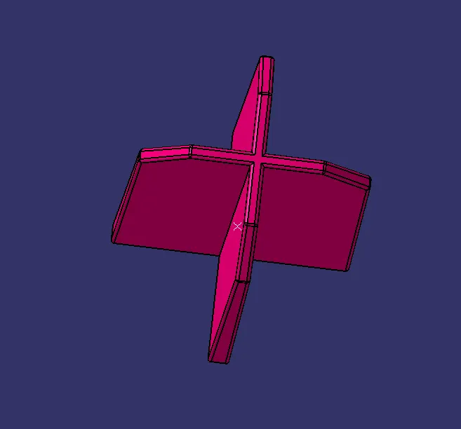
4 way locator:-
A round locating pin located concentrically in a hole is a common application of a 4-way pin, and helps to further secure the piece. 4-WAY LOCATORS: 4-way mean you prevent movement at 2 axes (+X, -X, +Y and -Y) on the plane. Generally, you have cylindrical pin on the fixture and circular hole at workpiece part.
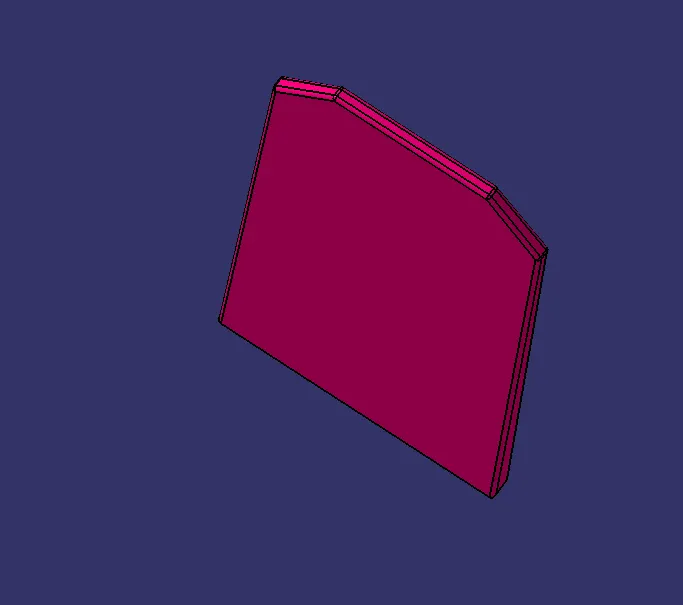
2 Way Locator:-
A 2-way locating pin restricts motion along 1 axis (or 2 degrees of Freedom), like a round pin in a slot. Likewise, a 4-way pin restricts 4 degrees of freedom along 2 axes.
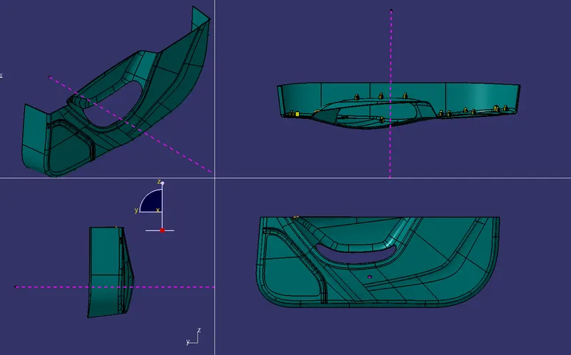
Given Class A Surface:
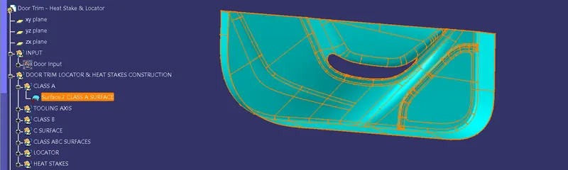
Before proceeed make sure there is no gaps in between the given Class A surface,visually we can check it or by clicking boundary command.
TOOLING AXIS:
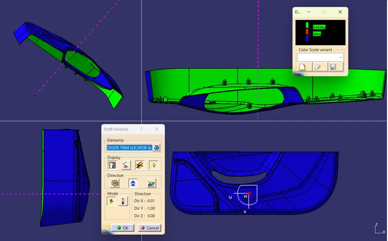
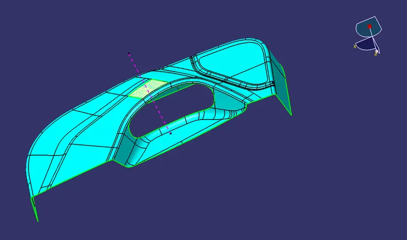
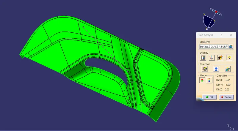
To create the tooling axis, I extracted a surface from class A and created a point in the middle of the surface by using the point command and created a line at that point through the x-axis. Now, I performed a draft analysis check from that line whether the created tooling axis is in the correct position or not. If in the draft, analysis check the surface highlighted with green colour on both sides of the surface the tooling axis is in the correct position and direction.
2. Tooling axis Bisecting Method:
To create the tooling axis, extract a surface from class A and create a point in the middle of the surface by using the point command and create a line at that point through the axis which looks a better path for the tooling direction. Now, name this line as the dummy axis. Create an axis system on the point created. Intersect the surface A and the planes from axis system. Now, create the lines at the ourter most side the surface which are int he direction towards the dummy tooling axis creater earlier. Bisect the line to get the tooling axis.
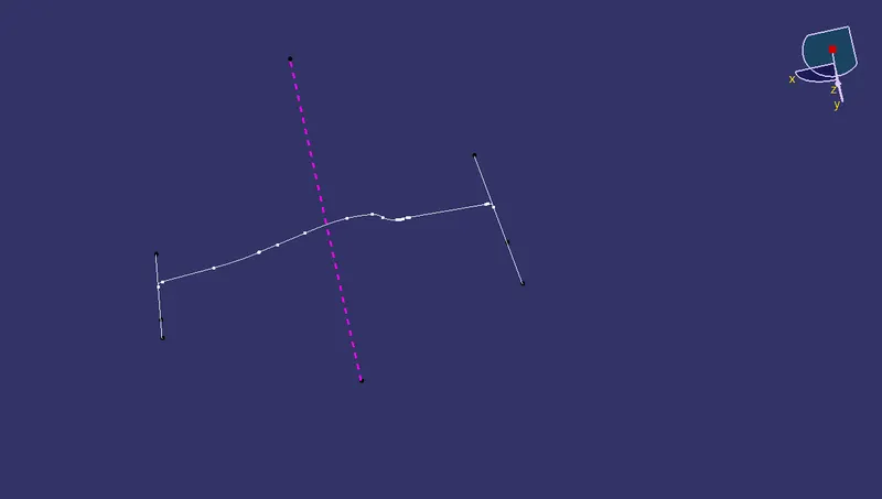
performed a draft analysis check from that line whether the created tooling axis is in the correct position or not. If in the draft, analysis check the surface highlighted with green colour on both sides of the surface the tooling axis is in the correct position and direction.
Draft:
The draft is the amount of taper for moulded or cast parts perpendicular to the parting. line. Draft angles are a design consideration that makes it much easier for a part to release cleanly from a mould. A draft angle is calculated as a degree measurement (or, less often, an inch or millimetre measurement) from the vertical axis of a mould, and it helps account for thermoplastic shrinkage, a practical reality of the injection moulding process for most materials.
Class B Surface:
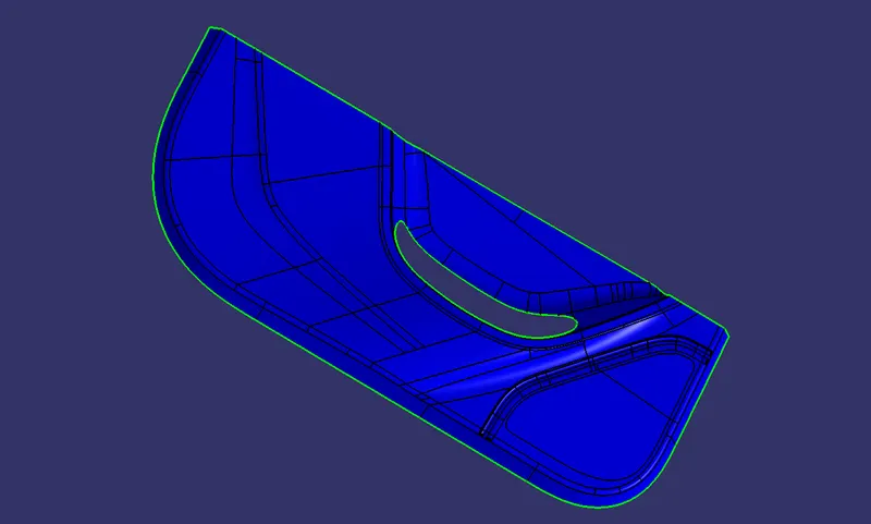
Create a B surface at an offset of 2.5mm with respect to the A surface given. We can notice that few of the elements will be missing after offset. Using features like the extract, extrapolate, multisection etc, fill up the missing elements.
The B surface will look as below after following the above procedure.
Class C Surface:
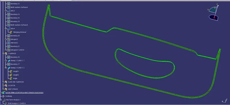
Using Sweep option Create the C surface as shown below.
Class ABC surfaces:
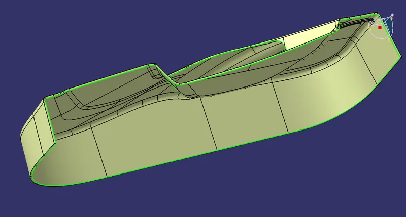
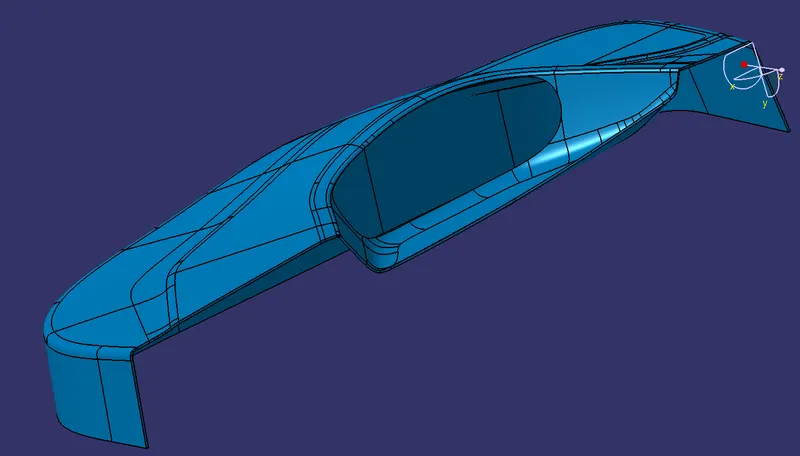
Join the C surface with the A surface.
Trim the B surface with the above surface to obtain a closed hollow body using surfaces.
Solid Part Body:
Convert the surface body into part body using the feature close surface.
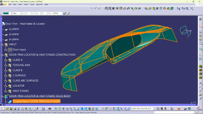
4 Way Locator:
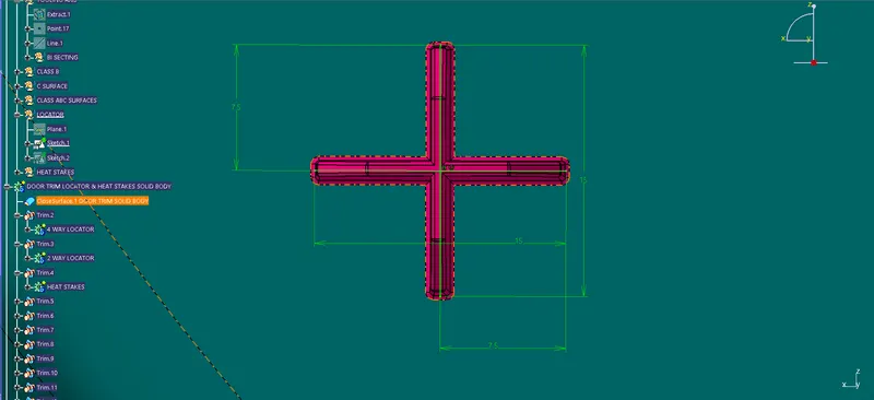
Create a 4 way locator using a sketch on the body. After creating the sketch, pad it 20mm in height and thicken it to 1.3mm and draft it with 0.5deg in the direction of the tooling axis. Give 5mm of chamfer with 45deg of inclination and a fillet of 0.20mm radius.
Use copy and paste the 2 nd 4 way locator using the translate feature.
Heat Stake:
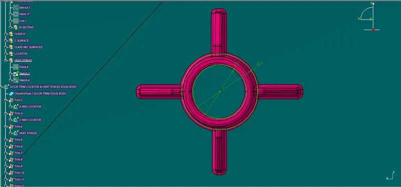
Create Heat stake. Draw a sketch on the surface. After the creation of the sketch, Pad it to 18mm height and a draft angle of 0.5deg on both sides (inside and outside) and then provide a fillet with a 0.20mm radius. After creating the heat stake, create the ribs for supporting purposes. To create the ribs, draw a sketch and padded it to height less than that of the heat stake and 1mm in thickness. After padding the ribs, drafted 0.5deg in the tooling axis direction and fillet it with a 0.20mm radius. Finally, use union trim on the ribs with a heat stake to remove the ribs as per the requirement, which are present inside the heat stakes.
Copy and translate the heat stake to all the positions as needed.
Perform draft analysis on the part. for inspecting the features which are added later on the B surface.