Week 10 - Challenge 3 - Door Trim Lower with Engineering Features
ans :-
Tooling axis :-
The tooling axis of the product tells us the direction of movement where the part is being produced effectively.
There are Some advantages if we follow the effective tooling axis like
The side cores and other things can be reduced.
The tooling axis has to be produced by considering some criteria’s like
Direction of movement
Bosses and other references have to be considered
Creating Tooling axis by using CATIA V5:
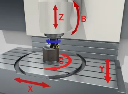
The above image shows the different directions where the tooling axis possible to produce.
The tooling axis is not restricted to a particular direction. It can be produced in that direction where the product can be produced easily.
Method :-
There are several ways to create a tooling axis we use this simple way to create the tooling axis.
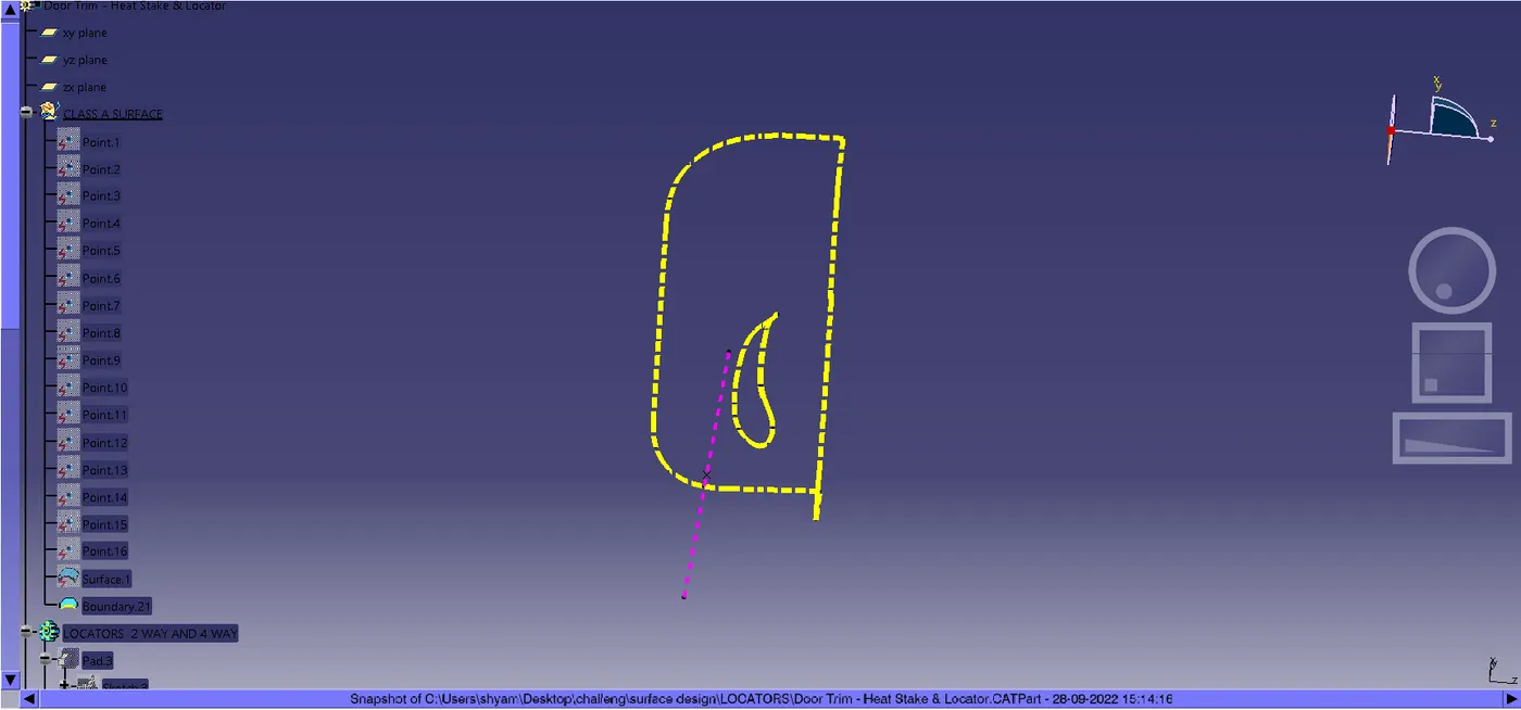 In the above picture the tooling axis is created by a using simple method
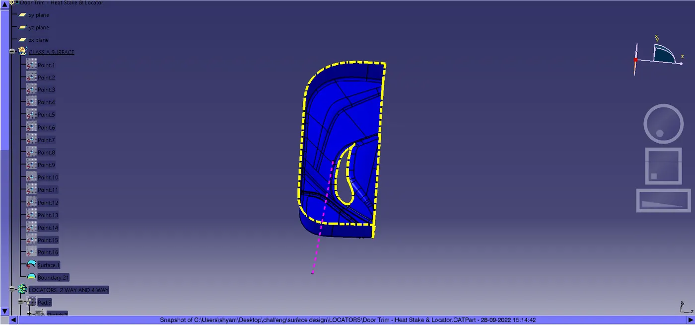
Step 1 :-
We extract the base of the component.
Step 2 :-
Deep point create on these surface in the middle.
Step 3 :-
The line creating on the extracted surface with the help of point to direction the line direction is perpendicular to the surface .
As shown in figure
Draft angle:
Usually draft angle is provided on the part and the core and cavity to reduce the wear and tear of the product while ejecting from the mold.
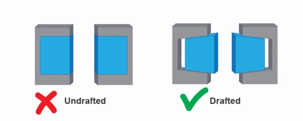
Draft analysis is nothing but the analyzing the draft angle provided on the part as well as the core and cavity of the injection mold by the Engineer.
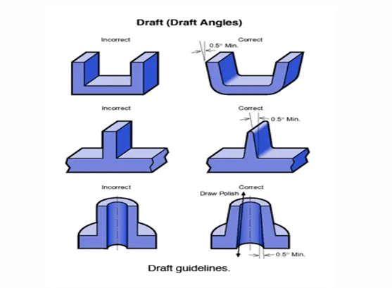
The draft angle allows ejector to simple push, to pop out the part from the mold
There are certain standards that should be followed to provide the draft angle on the parts, core and cavity.
Usually, the nominal draft angle 3deg is provided on the part
Providing the nominal draft angle is easy and very economical.
Draft angle is depending on the material which is being used to prepare the product.
Ex: Textured parts required more draft angle than the usual
There are certain standards that should be followed to provide the draft angle on the parts, core and cavity.
Usually, the nominal draft angle 3deg is provided on the part
Providing the nominal draft angle is easy and very economical.
Draft angle is depending on the material which is being used to prepare the product.
Ex: Textured parts required more draft angle than the usual
Draft Angle Of 1 To 2 Deg:
There is a thumb rule that the part with a depth of 2 inches requires a draft angle of 1-2 deg for easy removal of the part.
Steps to Analyze the Draft:
Step 1:-
To Analyze the draft angle first we need to turn on the draft analysis tool feature.
To turn on the draft analysis tool feature need to follow:
First we goes to insert toolbar select Analysis option and the clik on fractured draft analysis.
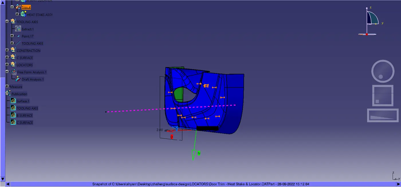

After selecting the new material, a pop-up is shown with several options, in those options needs to turn on the material type, and click ok.
Step 2: -
Check the draft angle of the faces by clicking the options available on the toolbar.
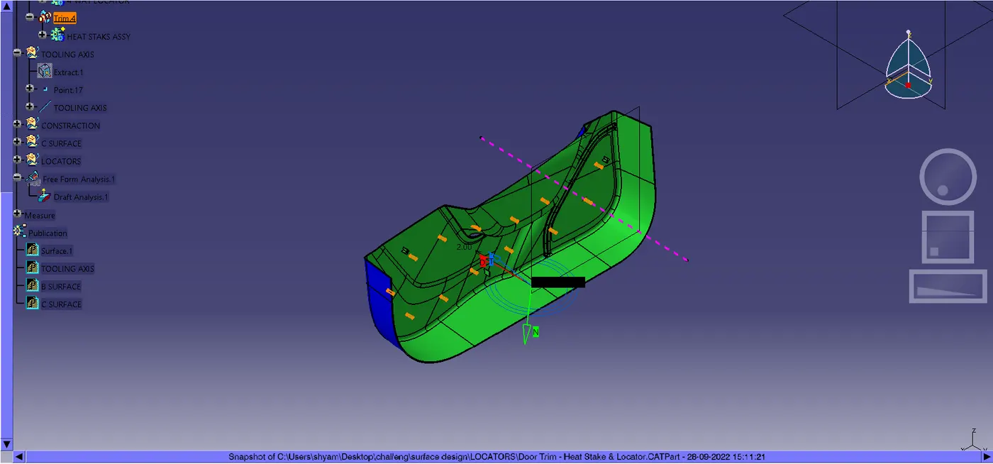
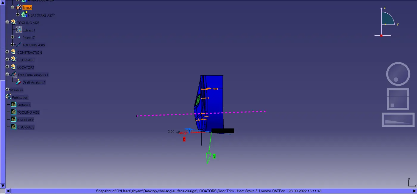
The popup below the draft analysis tool bar shows the range of the draft angle of the face with the different colors.
Figures