Week 10 - Challenge 3 - Door Trim Lower with Engineering Features
Step 1: The entire Class A surface was analyzed properly for any surface discontinuities and other irregularities.
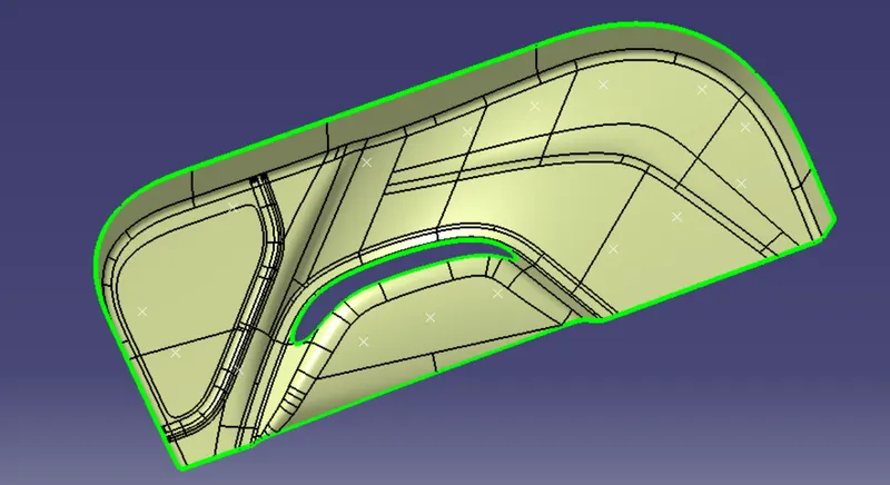
Step 2: Creation of Tooling Axis:
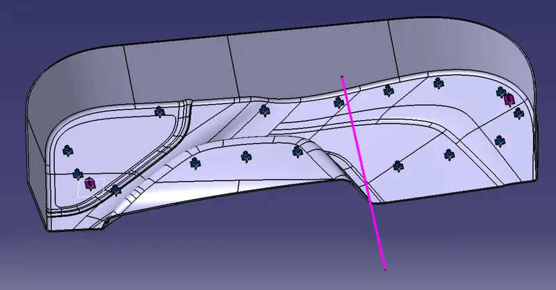
- A vertex on Class A was chosen through which the tooling axis passes. The tooling axis lies along the Y axis.
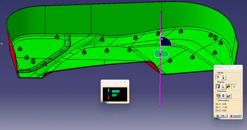
- Draft analysis was done on the Class A surface.
- This was clearing the 3 degrees draft.
Step 3 :
Step 3: Creation of Class B surface.
- An offset of Class A was taken just above it with a value of 2.5 mm.
- The missing surfaces were made taking offset of those individual surfaces: untrimming them, extrapolating them, and then trimming them together. And finally giving fillet to the edges.
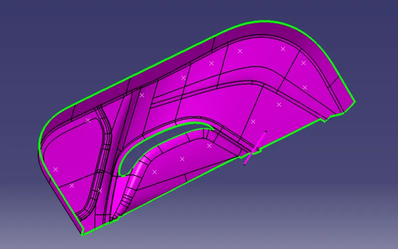
Step 4: Creation of Class C surface.
- The boundary of Class A was swept part by part with a draft of 3 degrees for the bottom boundaries and 90 degrees for the top boundaries.
- Then all of these individual swepts were joined together.
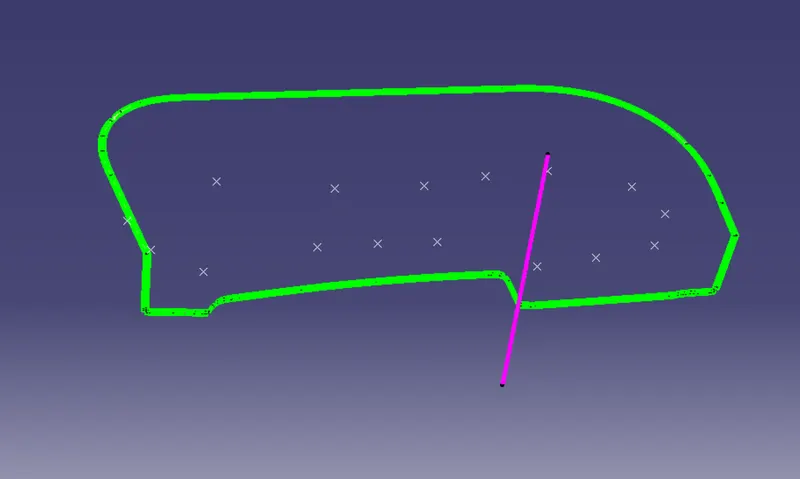
Step 5:Creation of Class A+C
- Class A and Class C surfaces were joined together.
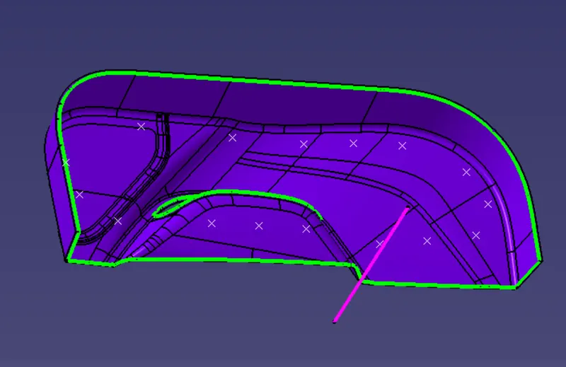
Step 6: Class A+C and Class B were trimmed together.
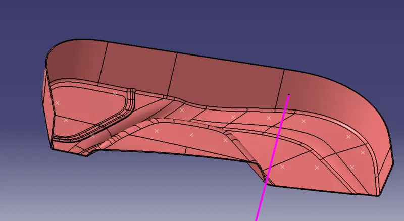
Step 7: Now this final trim was converted to a solid body using the Close Surface command.
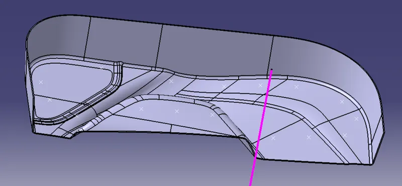
The engineering features:
4-Way Locator Geometry
- According to the reference image, a desired reference point was chosen and projected onto the B surface. The following sketch was made
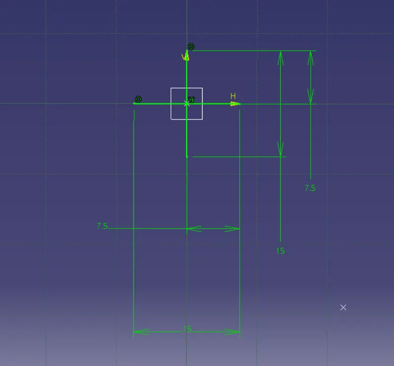
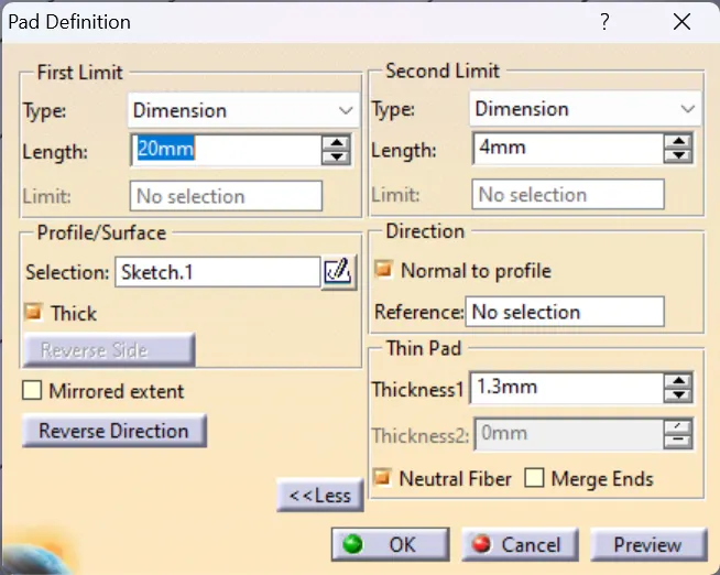
- This pad was extruded using the pad command in the mechanical part design workbench with following parameters
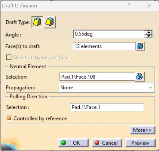
- Now all the side walls were given the following draft
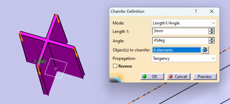
- The top edges were given a chamfer
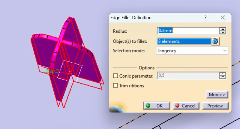
- Then side edges were given fillet
- The same was repeated on the other reference point.
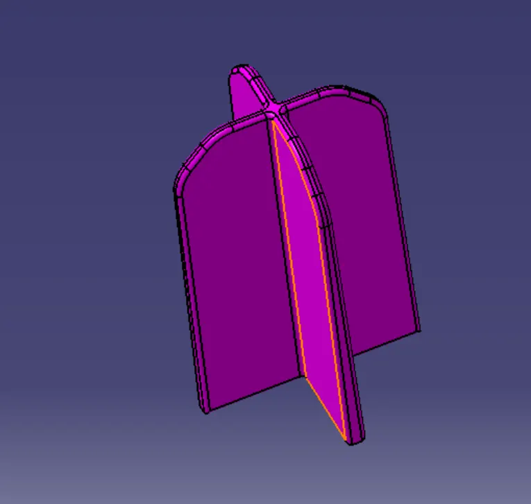
- Both of them were added to the main body
- Fillet of 0.25 mm was given to the contact edges
Heat Stakes:
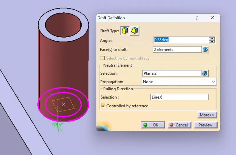
- The following sketch was made on one of the reference points and extruded up to 15 mm using the pad command, this was then given a draft of 0.55 degrees to the inner and outer walls.
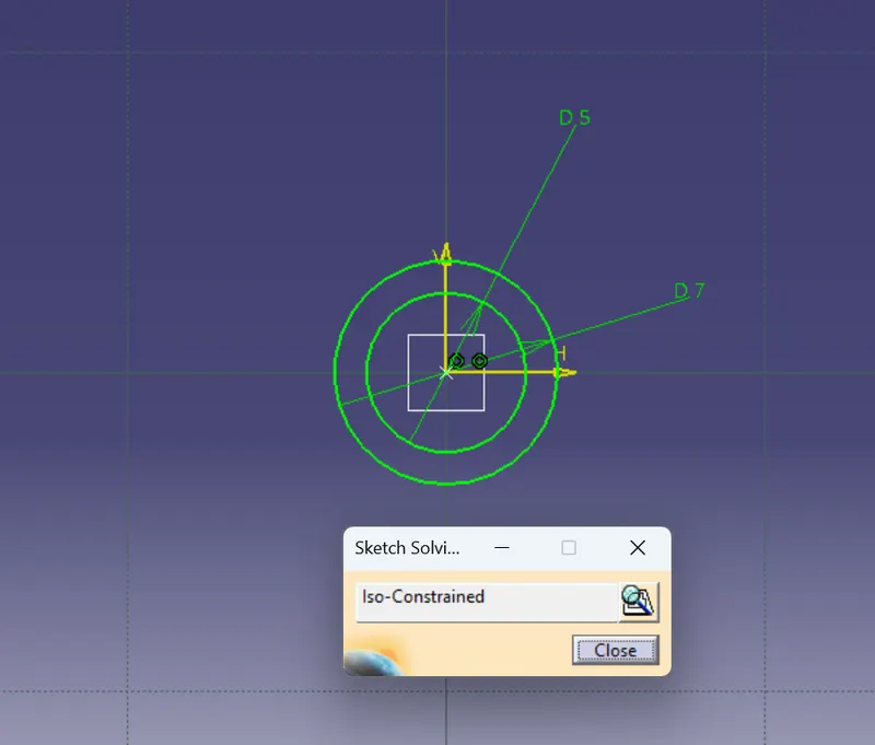
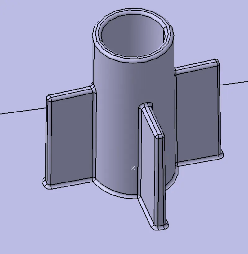
- Two lines were made passing through the center of the sketch and are perpendicular bisectors of each other.
- These lines were extruded up to 10mm and then thickened by 1 mm.
- These lines were added to the cylinder body using Union trim.
- A 0.25 mm fillet was provided to all the edges.
- Now these heat stakes were copied and then "paste special" the required number of times, and each of them was translated to desired reference points.
- All these were assembled together under "Heat Stake Assembl", and then added to the main body.
- Fillet of 0.25 mm was given to the contact edges
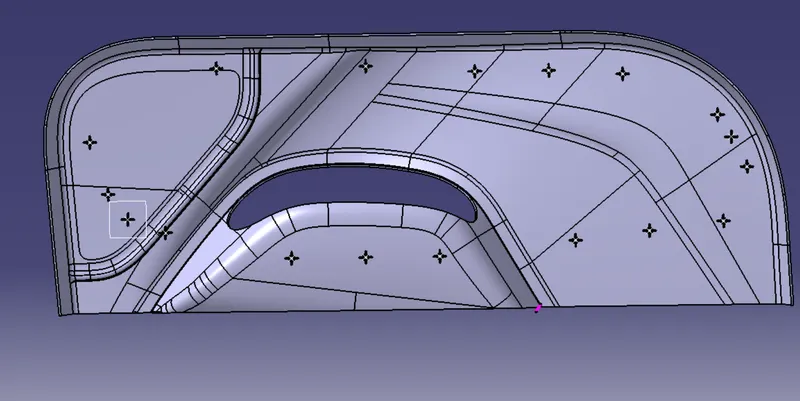
Draft analysis:
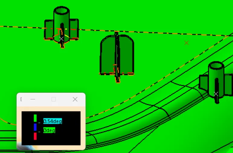
The engineering features are clearing the required draft of 0.55 degrees