Week 10 - Challenge 2- Attachment Feature Creation (Dog House)
Attachment Feature Creation - Dog House
Aim: Create a dog house for the door trim considering the design rules.
Theory:
Dog House:
Dog house is a engineering feature used in plastic part design. Dog housed are used as support feature. Sometimes other engineering features like snaps, locators and screw bosses are mounted on them for their increased strength.
Dog houses are subjected to draft analysis to prevent breakage of the component during the ejection from the mould cavity. Dog houses and other engineering features are created on the B Surface of the part.
Objective:
1. Create a tooling axis for the given class A Surface
2.Create class B and Class C surfaces of the door trim using the given class A Surface.
3.Create a final surface model and convert in into a solid body using the close surface command in the part design workbench
4.Create dog house on the B surface by considering the design rules.
5.Perform the draft analysis on the class A surface and the final part.
Design Methodology:
Class A surface means the visible surface. It gives the aesthetic of the component which is created by the styling team and gives to the part design engineer to create the part with all engineering aspects.
The given Class A surface is as below:
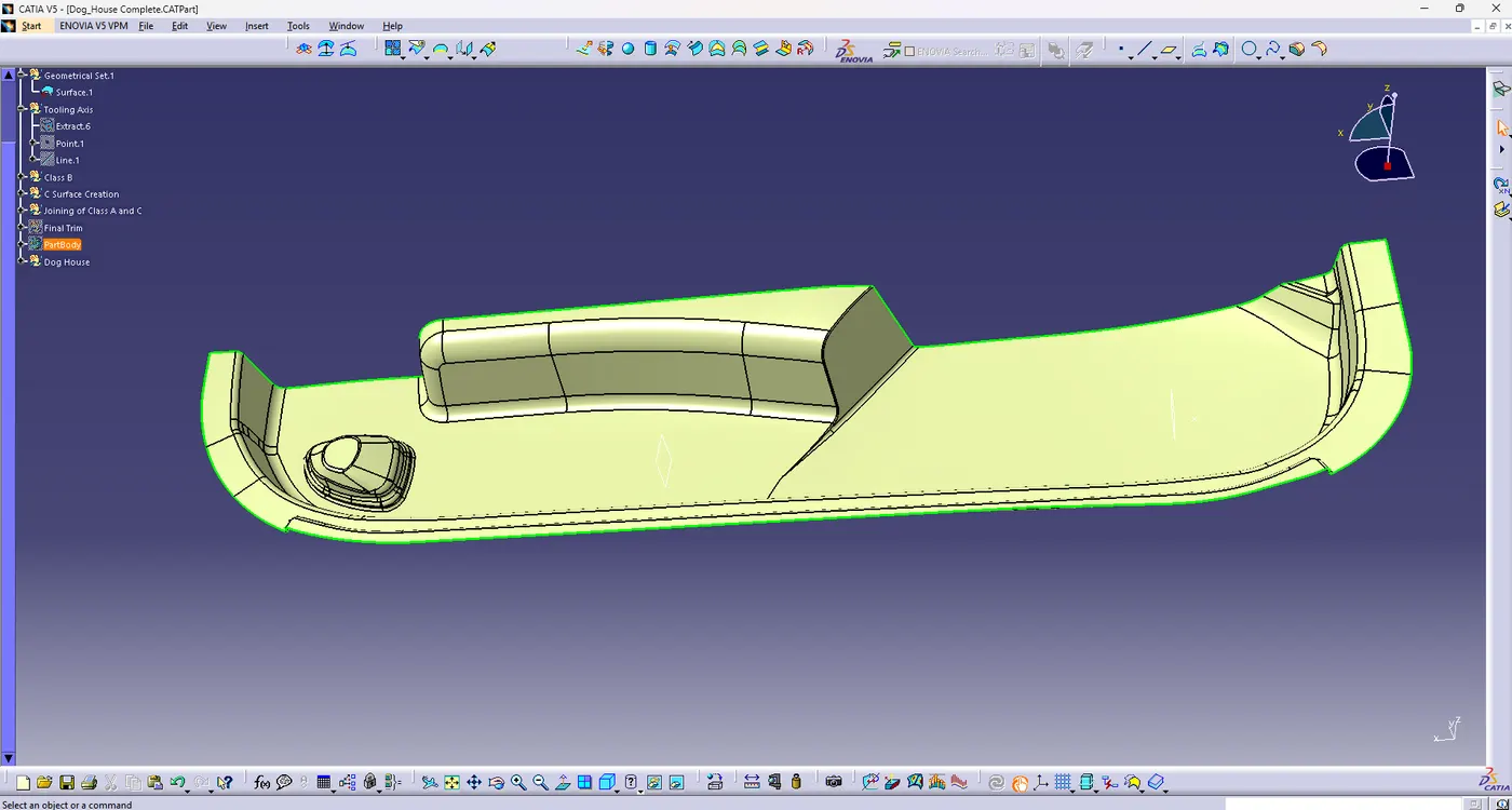
Check the continuity of the of the given surface and join the surfaces using the join command.
If there are no gaps in the Class A surface then proceed to creation of the tooling axis.
Tooling Axis Creation:
1. Check the best possible tooling direction by manually adjusting the compass
2.By analysis it is found that the y axis as tooling direction would clear most of the faces without any difficulties.
3.Now Extract any surface and create a mid point on the surface.
4. Then create a dummy axis creating a line on the point and direction along the y-axis.
5.Perform the draft analysis to find whether the given axis clears the draft analysis. If not create a new axis.
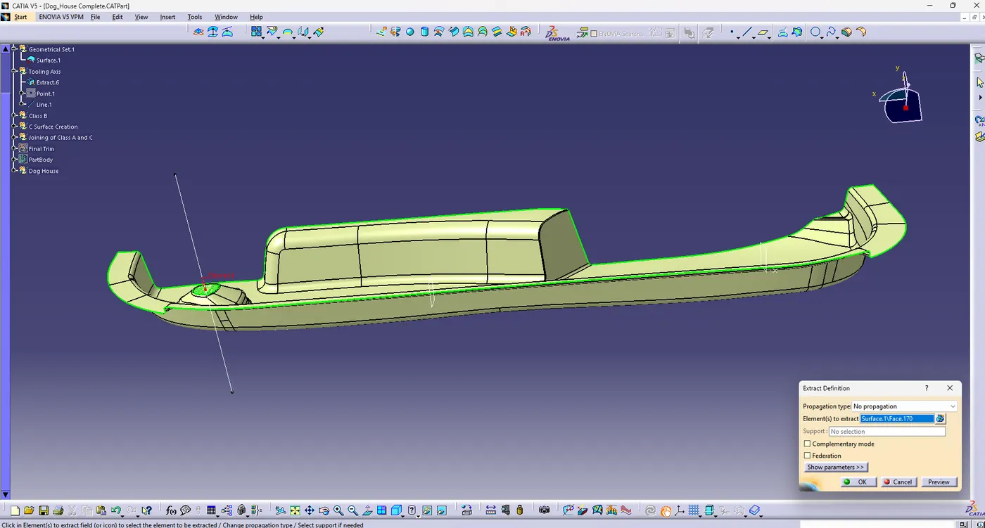
Then the tooling axis is created and the draft analysis is performed and the tooling axis cleared the draft analysis. 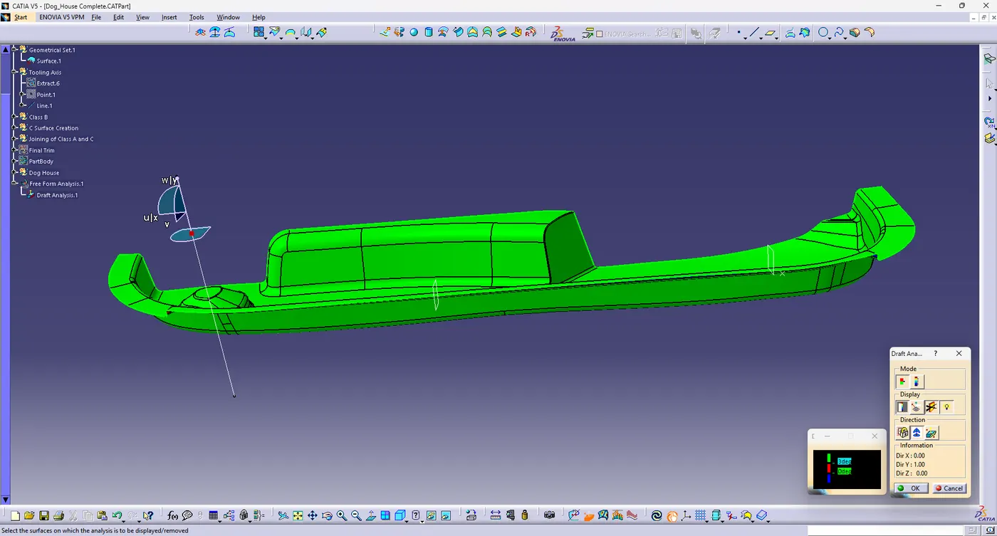
Class B Surface Creation:
Class B Surface means the thickness of the part it is not visible as it is inside of the part. In other words class B Surface is the surface below the certain thickness of the class A surface. This is the surface that contains all the engineering features of the part.
1. Create an offset surface of class A surface about 2.5mm inward direction.
2.Check for the discontinuity and rework on the off set surface using extract, multiple extract, extrapolate and trim features to remove discontinuities in the surface.
3. Joint the surfaces and ensure the class B surface has no gaps.
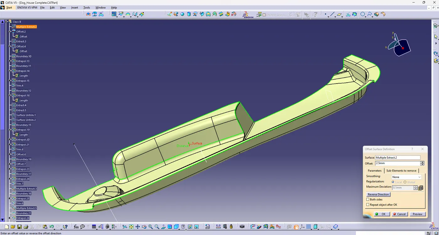
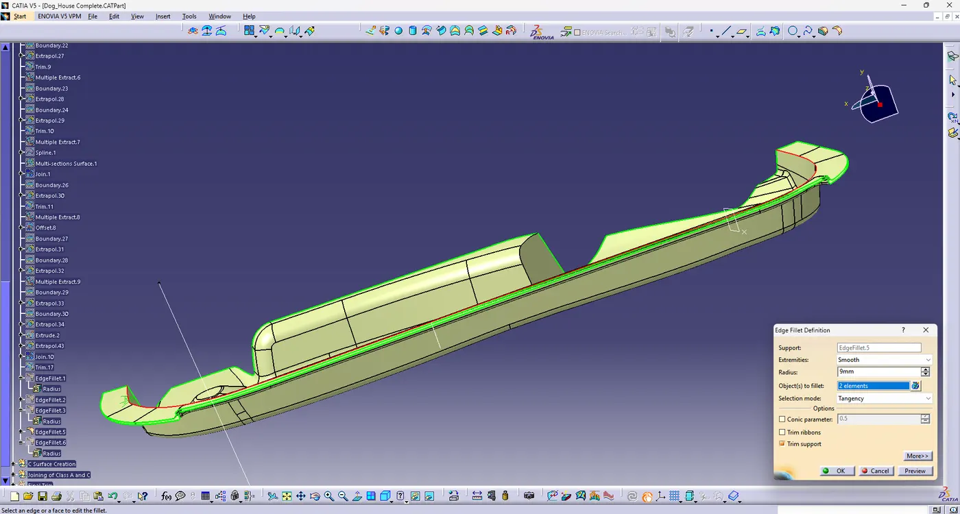
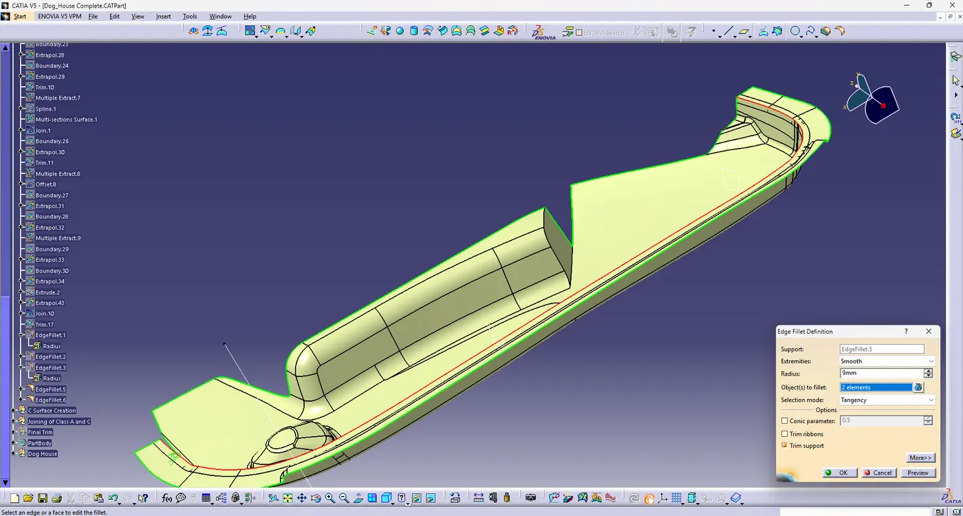
4. Then apply the fillets to the class B Surface based on the fillet radius on class A surface and the thickness of the part.
Class C Surface:
The surface that joins the class A and class B Surface is called the class c surface. Class C is often specified for the interior surfaces not readily visible, surfaces that will be covered by another part when part is assembled.
1.Create the sweep using the boundary of the class A surface and the tooling axis with required draft angle.
2. Join the Sweep surfaces by using the commands like extrapolate, multiple section surface and trim commands.
3.Finally join all the sweep surfaces and ensure the continuity of the class C surface.
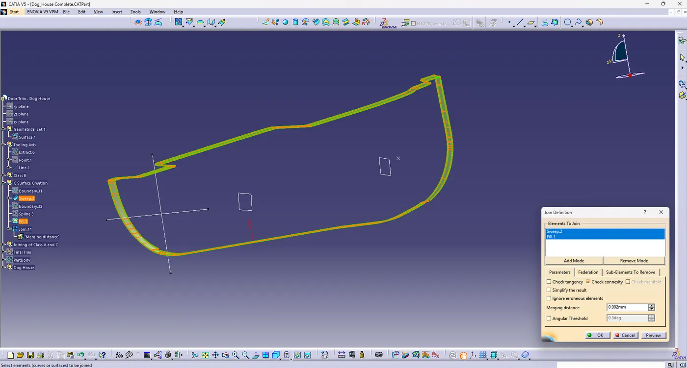
Creating the final Surface:
1. For creating the final door trim surface, join the class A and Class C Surface together.
2. Then extrapolate the B Surface in a little outward direction to make sure there would not be any gap when trimming with the joined surface.
3.Then trim the extrapolated class B surface with the joined surface of class A and Class C Surface.
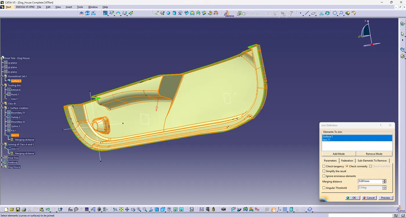
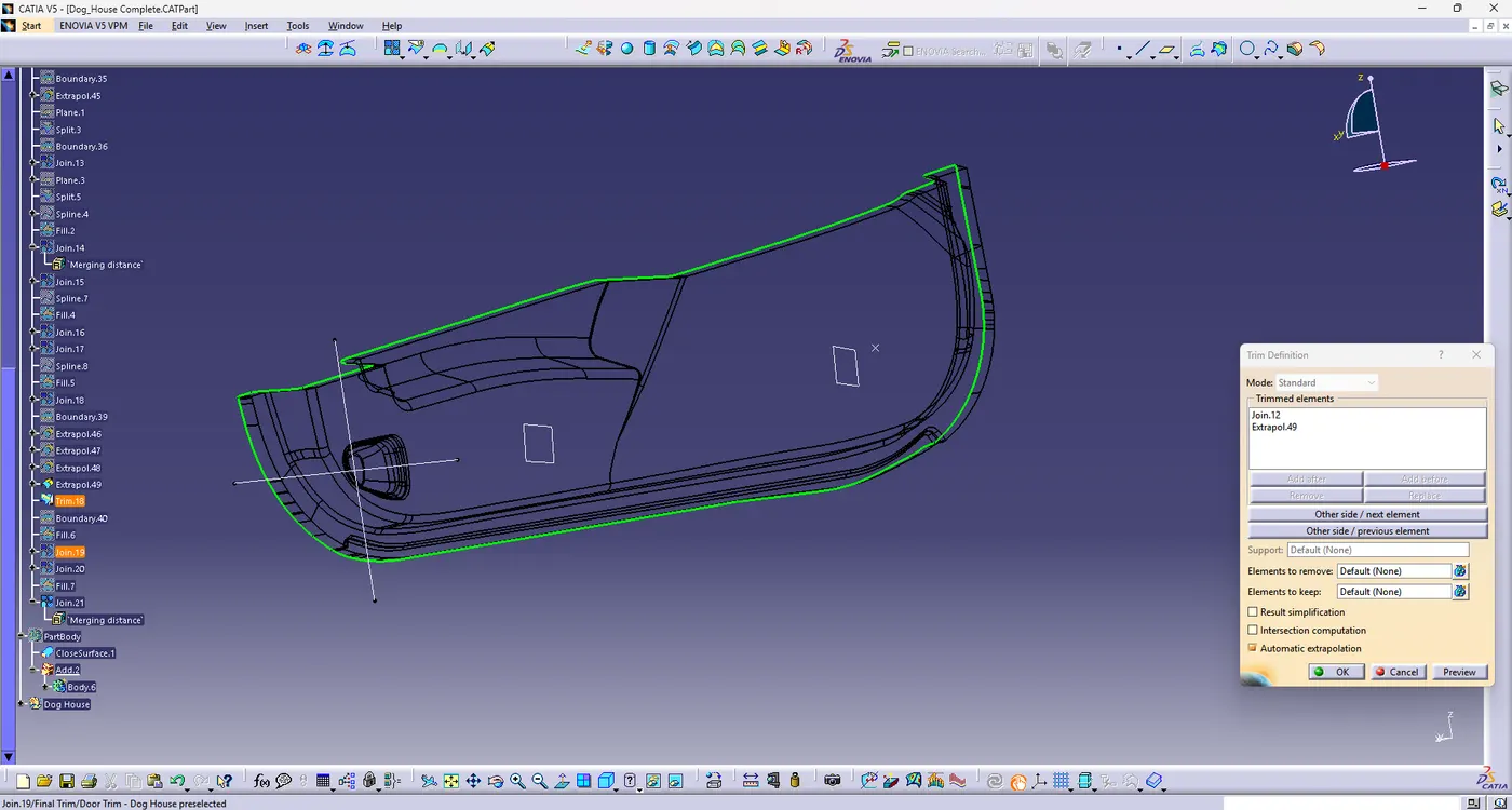
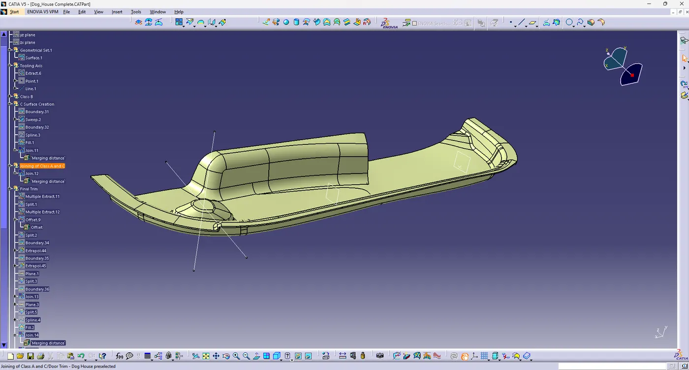
then make a solid part body using the close surface command in the part workbench.
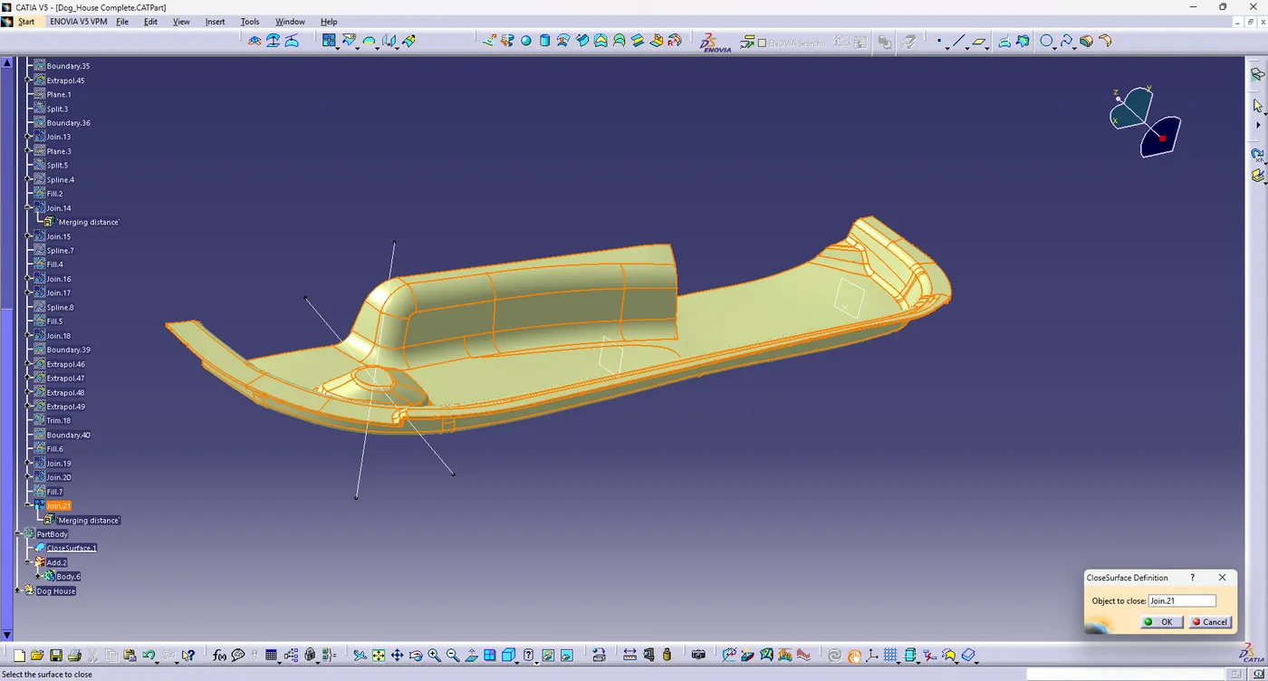
Dog House Creation:
Dog houses are designed to avoid sink marks, created on class B surface by screw bosses and to solve length issues when giving screw bosses which needed to be assembled to the other components.
It is also useful when perpendicular screw bosses are required on the part to the tooling direction.
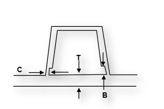
C thickness should be 40% of the main wall thickness T
Minimum width of the dog house is 12mm.
Height of B should be 3-6 mm
Minimum draft angle for the dog house is 5 degrees to die draw.
Procedure for creating a dog house:
The first step is to create a side core axis.
I have chosen the normal to point method for creating the side core tooling axis.
Create the dog house by creating a positioned sketch on the z-x Plane . Use extrude or sweep command to create dog house outer walls.
Now close the top wall using multiple section surface command.
Using thicken command in the part workbench, to create solid part of the dog house.
Give the proper draft angles and fillets by considering the design rules.
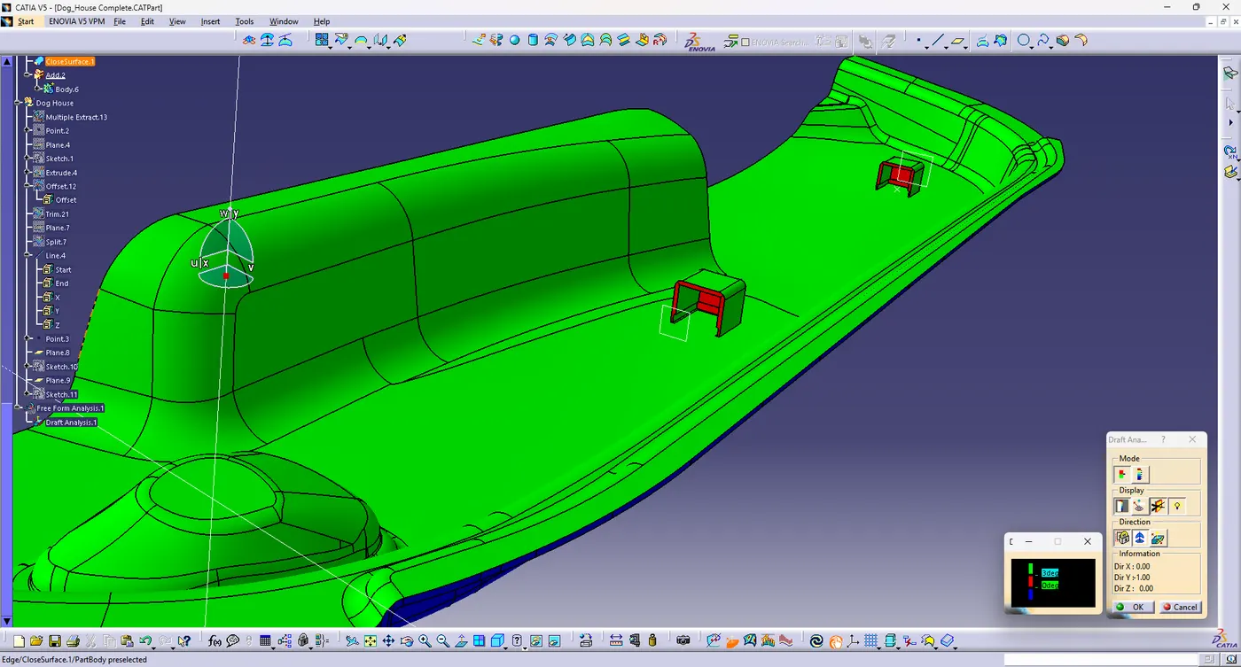
Conclusion:
The tooling axis and solid CAT part with B side feature is created from the given class A surface and draft analysis is performed.