Week 10 - Challenge 2- Attachment Feature Creation (Dog House)
AIM : To create the Door Trim Plastic Component from the given Class A Surface & then create two dog houses as attachment features for it while following the issued Design Guidelines.
Use case of Dog-House in any Plastic Component: The dog-house is an engineering feature used in the plastic trim design that is used as a supporting feature. Sometimes other engineering features like snaps; locators etc. are mounted on them to increase their strength. Usually, this engineering component is built on the B-surface and is subjected to draft analysis to prevent breakage of the component during ejection from the mould cavity.
Wall Thickness: Thick sections waste material and are simply uneconomic. So solid shapes that would do the job well in wood or metal must be transformed to a 'shell' form in plastics. This is done by hollowing out or 'coring' thick parts so you are left with a component which regardless of complexity is composed essentially of relatively thin walls joined by curves, angles, corners, ribs, steps and offsets. As far as possible, all these walls should be the same thickness. The Wall thickness guide range is 0.75 mm to 3mm for reinforced materials and 0.5 mm to 5 mm for unreinforced materials.
Fillet Radius: Properly designed corners will make a big difference to the quality, strength and dimensional accuracy of a moulding. But there is another benefit too. Smooth curved corners help plastic flow in the mould by reducing pressure drops in the cavity and minimising flow-front break-up. Internal radii should be at least 0.5 and preferably 0.6 to 0.75 times the wall thickness.
Draft Angle: Tooling must be cleared for easy ejection of the component, from the core cavity. In order to clear tooling certain value of draft is given to the component. A minimum of 1-3deg is provided on all plastic components.
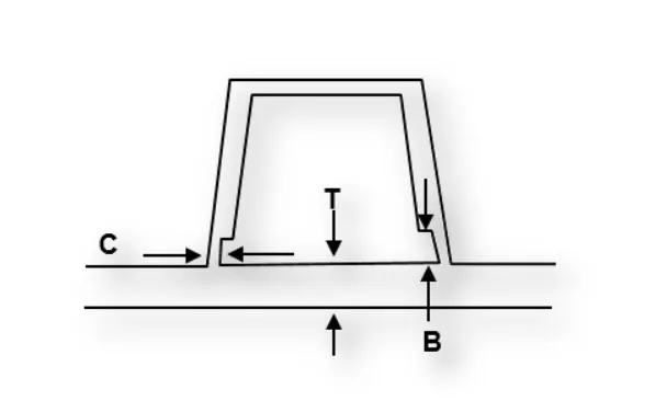
DESIGN GUIDELINES FOR DOGHOUSE IN THIS CHALLENGE:
-
Doghouse wall thickness at the intersection of the part wall ( C ) should be 40% or less than the main wall stock ( T ).
-
The height of ( B ) should be between 3.0 – 6.0 mm
- The draft angle with respect to the Main Tooling Axis should be 3 degrees & the Side Core Axis should be 1.5 degrees.
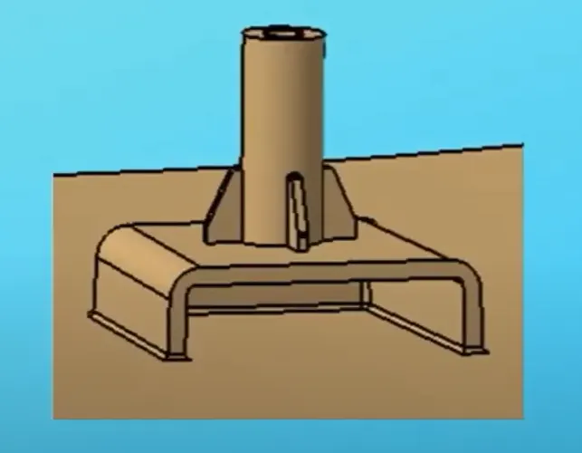
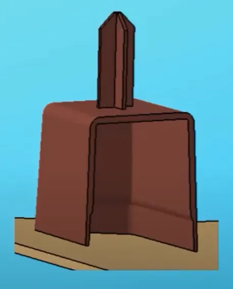
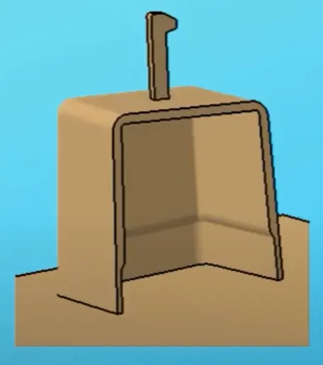
Examples of Doghouses with Screw Boss, Locator & Snap Head respectively:
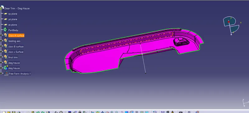
First, we will begin by checking the State of Connectivity for the Class A Surface and ensure that there are no gaps between the surfaces as all the surfaces should be joined well together with each other and shouldn't consist of any discontinuities between them.
Our Class A Surface:
There are two methods to inspect the State of Connectivity for the Class A Surface:
1. Using the 'Join' Command' from the 'Operations Toolbar':
First, we'll click on 'Join Command' and select our Class A Surface. Then, we have to ensure that the 'Check Connexity' option is marked as shown in the images below. It will check for any gaps that may be present between our surfaces. Then, we'll click on the 'Preview' button and if it doesn't show any 'Connexity Error' on our surface then it means our surface is well-connected and there are no discontinuities between it.
2. Using the 'Boundary' Command' from the Operations Toolbar:
In this case, we have to click on the 'Boundary' command and then select the Class-A Surface. After that, we'll click on the 'Preview' button to highlight all the boundaries that are on the Class-A surface and check if there are any internal boundaries other than the outer edge boundaries.
PROCEDURE TO CREATE THE MAIN TOOLING AXIS:
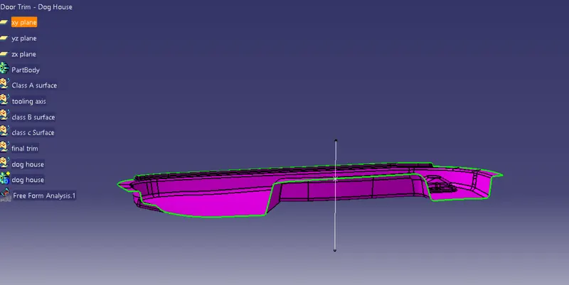
Class-A surface is first analyzed to create the tooling axis. where the molds pull apart in injection molding. Tooling direction is essential for plastic product design as it decides the direction for mold separation. To create the tooling axis first we have to check the best suitable direction for tooling by using the compass. the y direction is suitable for creating the tooling axis because in the y direction most of the surfaces are clearing while performing draft analysis. Generally
tooling axis is created using bisecting line method but here A line normal to the surface is created in the y direction and considered the tooling axis.
DRAFT ANALYSIS FOR THE CLASS A SURFACE USING THE MAIN TOOLING AXIS FROM THE FIRST METHOD:
Now, We will perform a Draft Analysis on the Class A Surface itself using the Main Tooling Axis created using the First Method:
Before starting with a Draft Analysis Operation, we will go to the 'Customize View Parameters' option under the 'View Toolbar'. Then we will enter the 'Customize View Mode' where we will go under the 'Mesh' option and select 'Material' and press 'OK'.
To start the Draft Analysis in the 'Generative Surface Design Workbench', we will go to 'Insert' and then look for the option called 'Analysis'. Once found, we will go under that and click on 'Feature Draft Analysis. This will open the 'Draft Analysis' Dialogue box. There, we will ensure that under 'Mode' we have selected 'Quick Analysis', under 'Display' we will select 'Show or Hide the Color Scale' and then select '3 Degrees' as the permissible draft angle. Then, under 'Direction' we will choose the icon with the symbol of the compass on it which stands for 'Use the Compass to define the new current draft direction'.
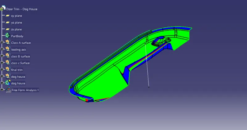
If this project needed to be created in a real industrial environment then we have to contact the Class A Surface Designer and ask them to fix these regions but since this is just a challenge we're going to proceed with it anyway.
It is evident from the above image that the Draft-Analysis on our Class A Surface was successful for the degree of 3 degrees.
Hence, we can see that the Draft Analysis was successful along the Main Tooling Axis.
PROCEDURE TO CREATE THE CLASS B SURFACE:
We'll start the procedure by creating an offset for the entire Class A Surface at a distance of 2.5mm as that is the desired thickness for our final plastic component.
As this is a complex surface hence the offset will fail to offset every element according to our necessity. It'll select some sub-elements that belong to the filleted regions by themselves that we have to remove to get the rest of the surface that is offset.
Class B Surface after 2.5mm Offset:
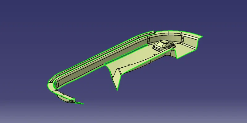
Now, we're going to fix these patches by recreating these sub-elements using various tools such as Extract, Offset, Untrim, Extrapolate, Multi-Sections Surface, Trim, etc.
Fixed Class B Surface:
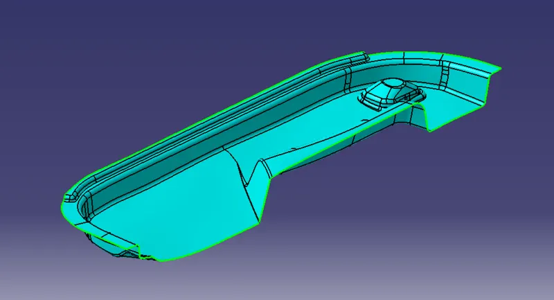
PROCEDURE TO CREATE THE CLASS C SURFACE:
We'll create the Class C Surface with respect to the Class A Surface and provide draft angles to those surfaces that are parallel to the Main Tooling Axis. Surfaces at the bottom won't be needing any draft angle as they'll get cleared by the core itself. To create the Class C Surface we have to use various commands such as Sweep with Reference Surface and With Draft-Direction depending upon the necessity and at places where it'll be difficult for us to create a surface using Sweep, we'll use Multi-Sections Surface to create those surfaces. The draft angle will be 3 degrees.
Using Sweep Command with Draft Direction to create the C Surface:
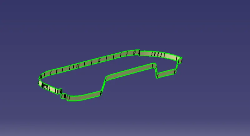
Finally, we'll join the Class A & Class C Surface together. Then, we'll create an intersection with the Class B Surface and check if it is feasible to trim with each other. After inspecting the intersection, we noticed that the Class B Surface was not intersecting with the Joined surface of Class A & C and hence we extrapolated the Class B Surface as shown below:
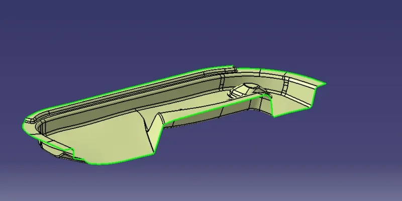
After this we trimmed the extrapolated Class B Surface with the joined surface of Class A & C as shown below:
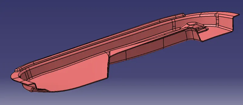
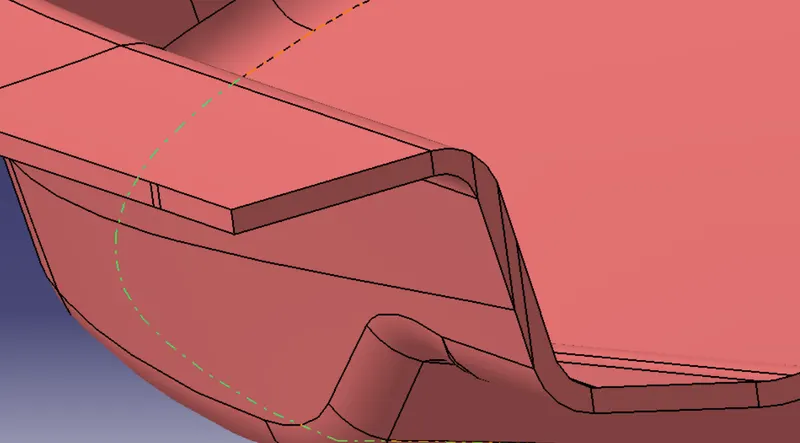
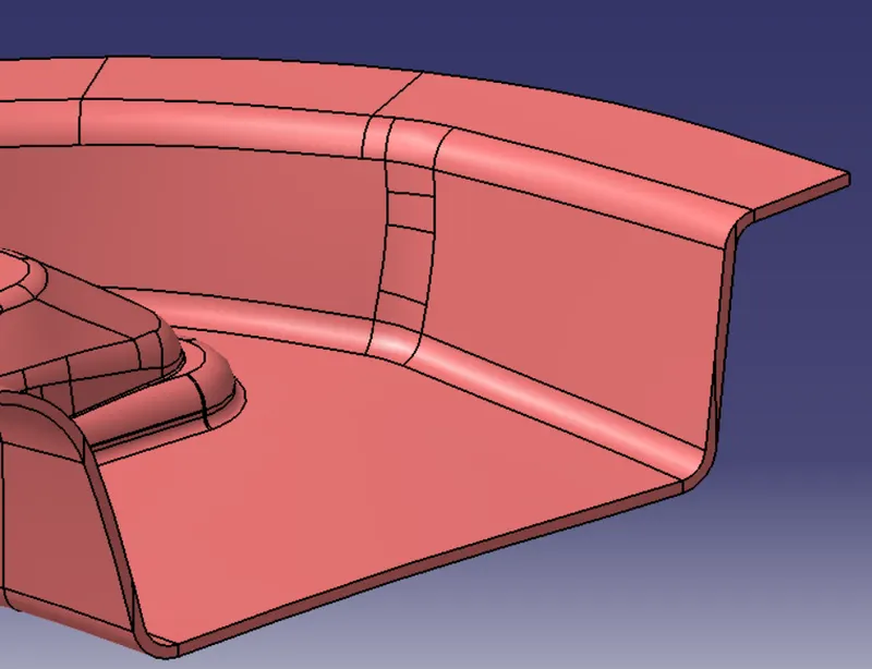
To check whether this body is closed or not we'll use the Boundary Command on it as shown below:
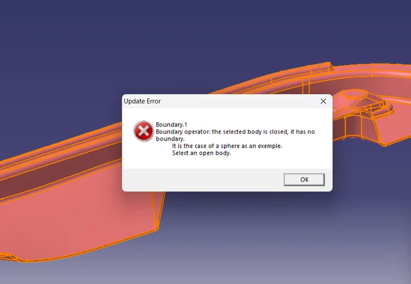
From the above image, we can see that the final closed body doesn't have any boundaries, and hence our final closed body is obtained successfully.
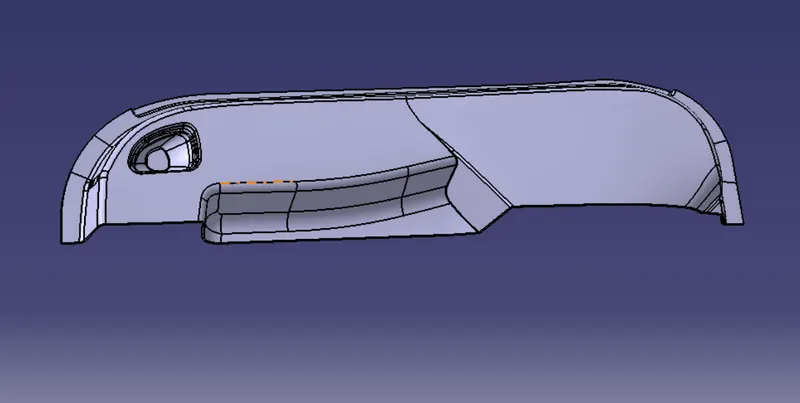
Finally, we'll go to the Part Workbench and use the option 'Closed Surface' from the 'Surface-based Features' toolbar to convert the final trimmed body into a solid body as shown below:
PROCEDURE TO CREATE THE DOGHOUSE:
Reference Image provided for the construction of two doghouses:
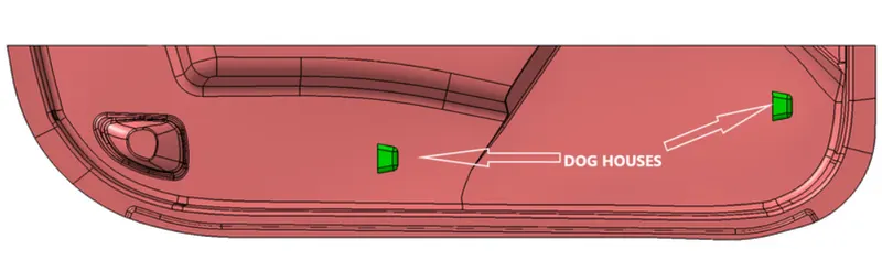
It is just a reference image and doesn't exactly adhere to all the design rules but we have to take the reference image into account to create these doghouses on our plastic component.
First, we'll begin by creating the sketch for the doghouse as shown below:
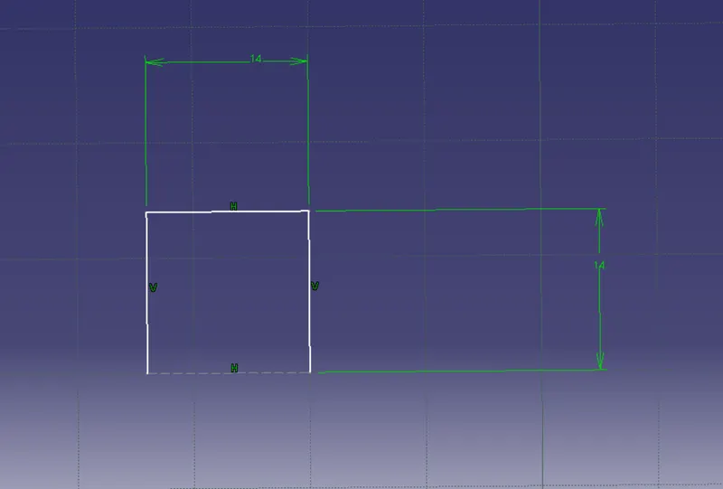
From the sketch, we can see that the width of the doghouse is more than 12mm which is one of the design rules. We cannot go below that value.
Then, we'll use the Sweep Command with the Draft Direction to provide a draft angle of 3 degrees with respect to the Main Tooling Axis.
From the above image, we can see that 1.5 degrees draft angle is provided to the sweep surface.
After this, we're going to use the Multi-Sections Surface command to create the top face of the doghouse as shown below and join it with the sweep surface:
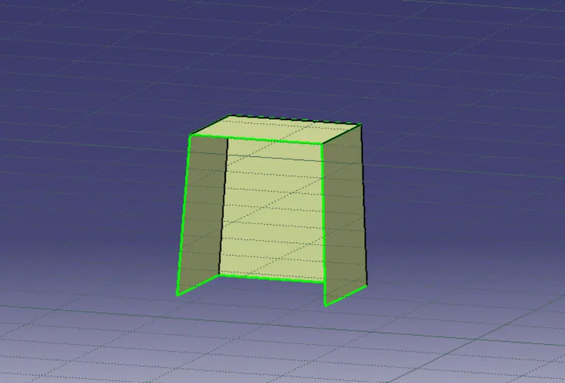
Now we're going to move on to the Part Workbench and use the Thick Surface command from the Surface-based Features toolbar to thicken the surfaces by 2mm.
Then we're going to provide a draft angle of 1.5 degrees to all the adjacent faces as shown below using the Draft Command in the Part Workbench.
After this, we're going to remove the material from the lower section of the doghouse for coring and to do that we going to use create a base surface of the doghouse using the Multi-Section Surface command and then offset it by 4mm. Then, we used the Multi-extract command to extract the inner faces of the doghouse and trim it.
Now, according to the design rule, the thickness of the coring section's wall should be 40% value of our part's thickness and 40% of 2.5 is 1mm and our current wall thickness of the doghouse is 1.685mm. Hence, we're going to offset this trimmed surface by 0.685mm and extrapolate it so that we can use the Split Command from the Park Workbench to remove material from the doghouse.
After that, we'll provide a draft angle of 1.5 degrees to the newly formed surface made using the coring operation.
Finally, we're going to provide all the necessary edge fillets on the required surfaces.
Hence, our doghouse is finally complete and we'll make the second house following the same design rules.
Now, using Boolean Operations, we're going to assemble these doghouses with our main plastic component and create the final part as shown below:
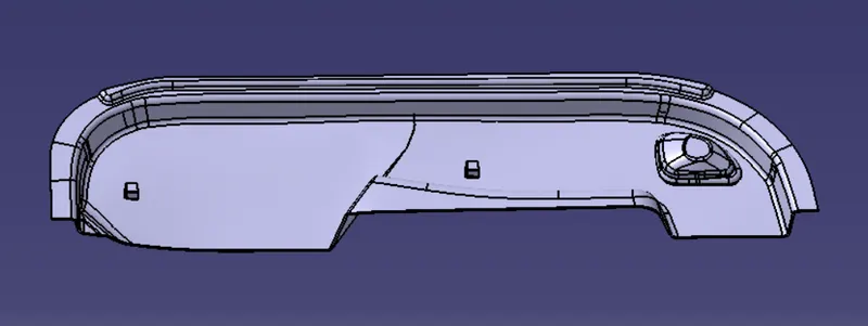
DRAFT ANALYSIS ON THE FINAL PLASTIC COMPONENT WITH ATTACHMENT FEATURES:
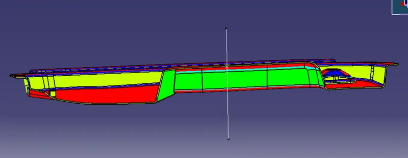
From the above image, we can clearly see that the draft analysis was successful and every necessary surface is clearing the draft angle.
Conclusion :
Hence, the dog house for the door trim was created by considering the design rules, and
the Draft analysis performed on the final component is successfully done.