Week 10 - Challenge 2- Attachment Feature Creation (Dog House)
Solution - A complete report and steps followed is mentioned below -
Given class A surface -
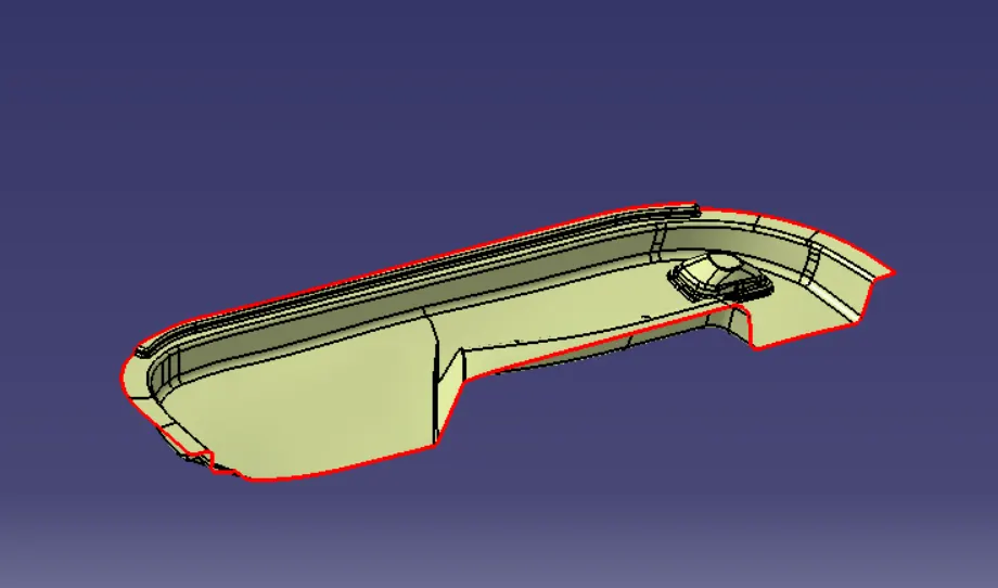
STEP 1: Check the connectivity of the Class A Surface to ensure that there is no gap between the component, using the join command.
STEP 2: - Create Tooling Axis
Tooling axis -
Tooling axis or Molding axis is the direction in which the core and cavity opens. It is basically the direction that the mold pulls apart. It is created using Bisecting method. Creating a tooling axis is necessary to provide draft angle and analyze them.
Bisecting Method to creat Tooling Axis -
To decide the Tooling axis, the component should clear the tooling axis in the given specific direction. The first step is to visually check the component for the best tooling direction in all three x, y and z directions. In the given Class A surface it is found that the best tooling direction is Y axis as the irregularities present on the surface cannot be cleared in either Z or X directions with minimum tooling. So Y direction is chosen for Tooling axis.
In bisecting method tooling axis is created by taking a intersection on class a surface then take the 2 inclined line and performing bisecting line command over it, then we get a bisecting line which we call tooling axis.
In this Model during visually check it is found that Y axis (in maximum flat surface area of model as shown) is best possible direction to create tooling axis and in the draft analysis this axis is also clearing, so we can take it as a tooling axis.
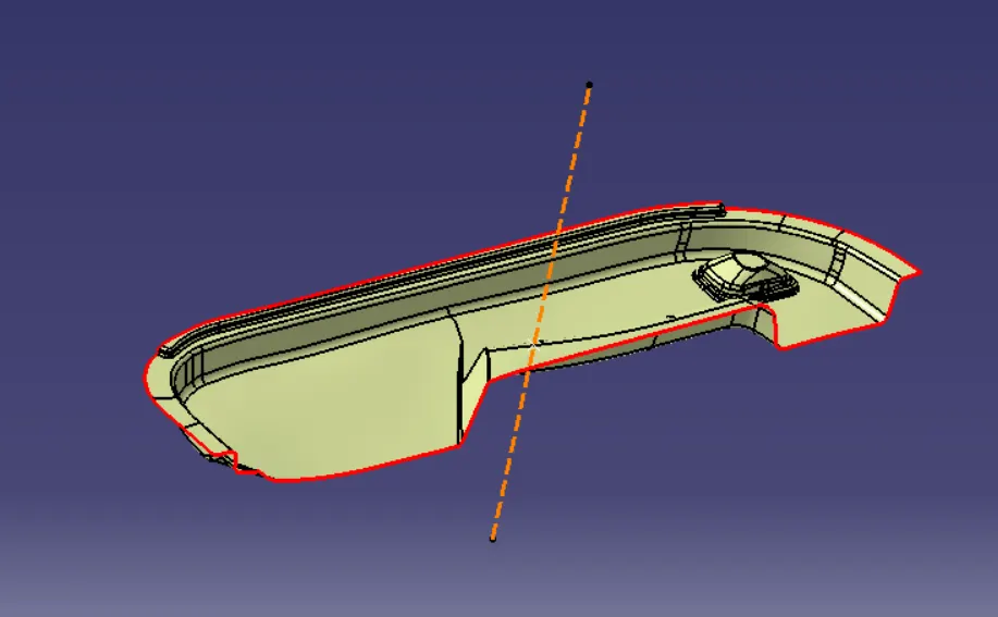
STEP 3 : - Draft analysis of class A surface -
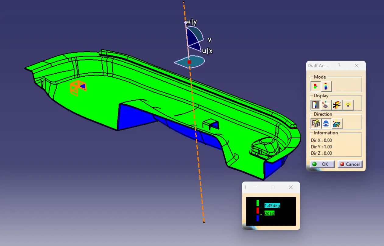
For Draft analysis first we fix the draft compass axis with tooling axis then we give the draft angle and check for its feasibility of occurance which is shown by color grade as shown in picture below -
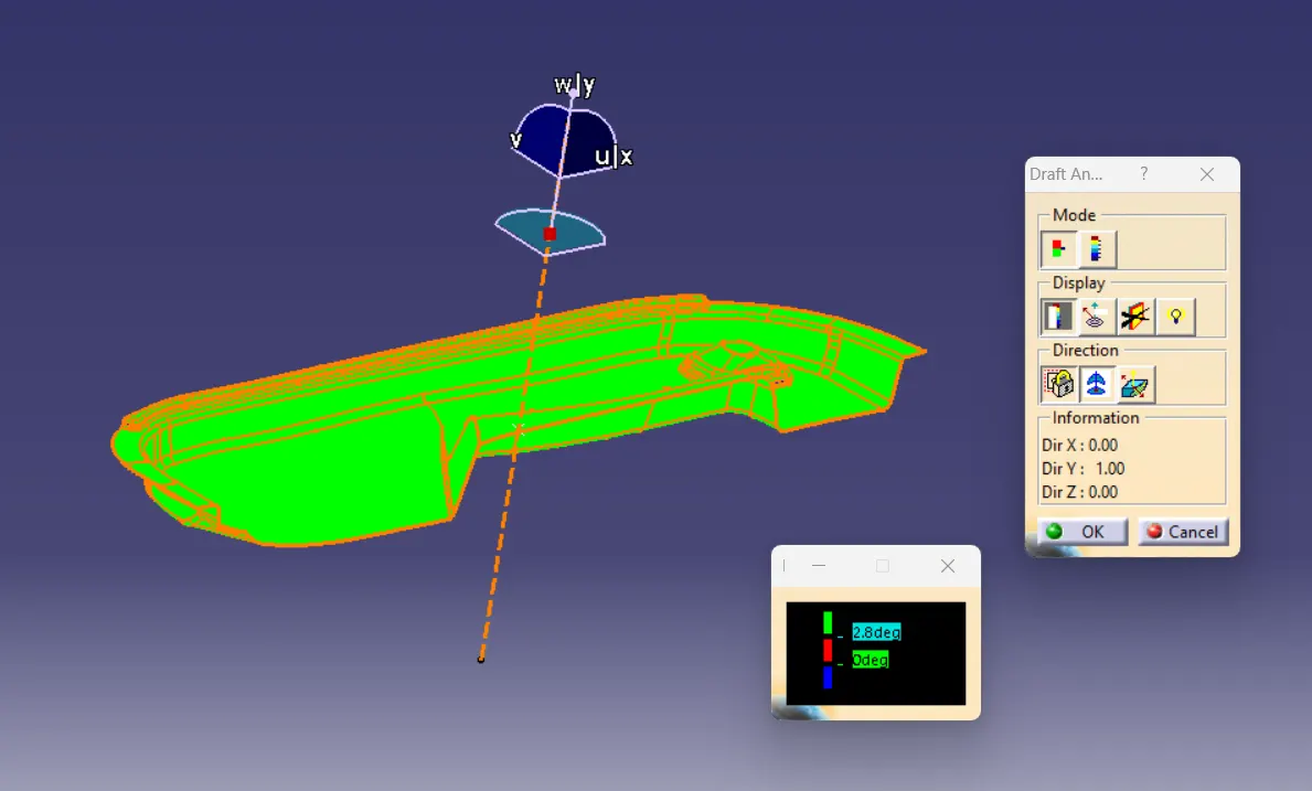
Here in some area we are not getting proper draft this error is happening because in given Class A surface those area is not provided proper draft.
STEP 4 :- Creation of Class B and C surface -
This is done by using all necessary surface command which is attachted below in a CATPart file and the Screen shot of B and C surface is attached here below -
B surface -
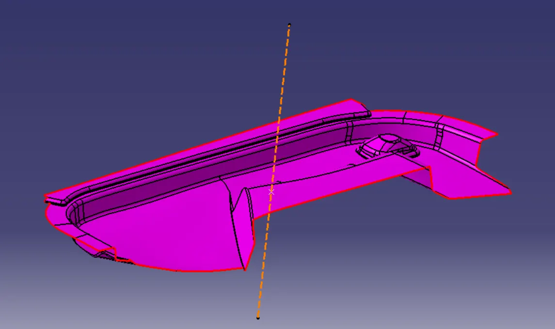
C surface -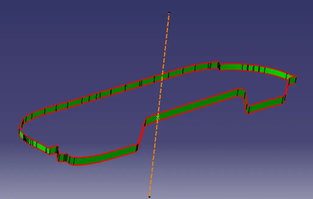
STEP 5 :- Complete Surface creation Using Class A , B and C surface -
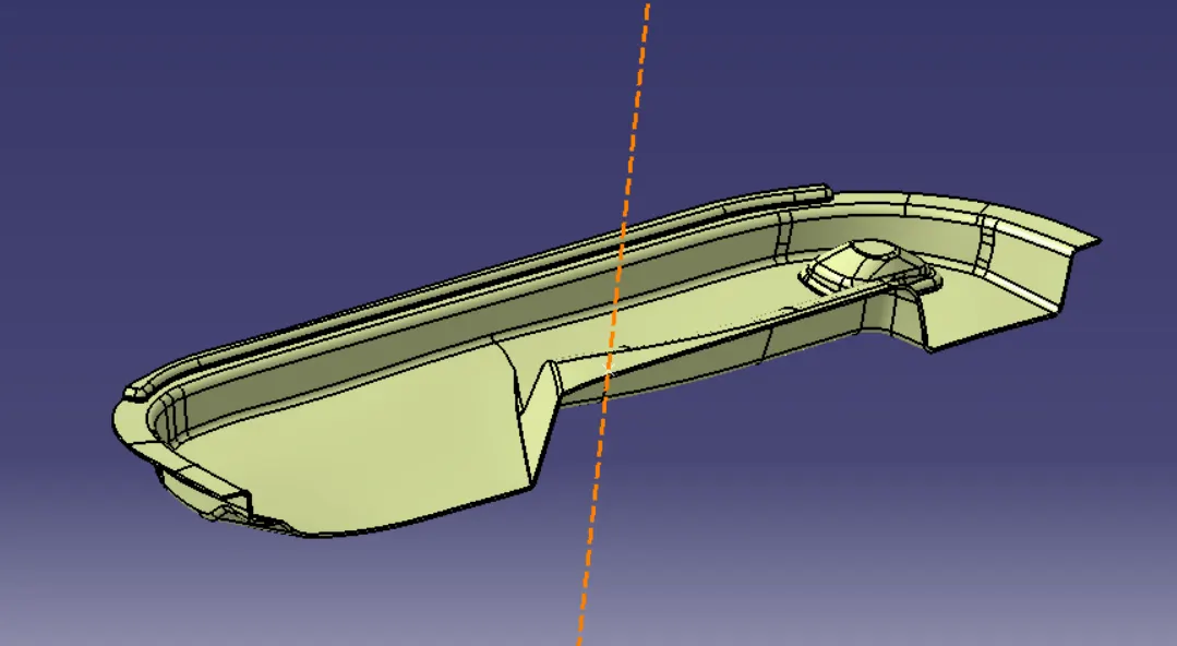
STEP 6 - Conversion of surface body into solid body using close surface command of part workbench-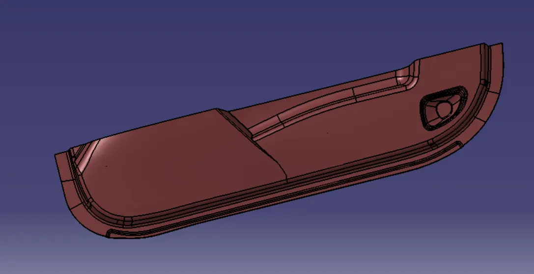
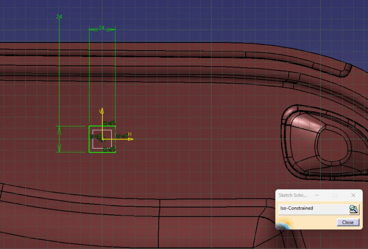
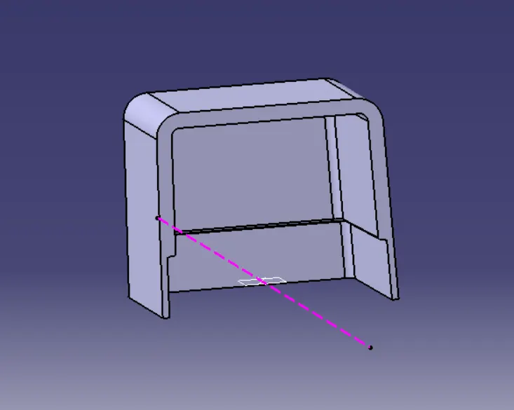
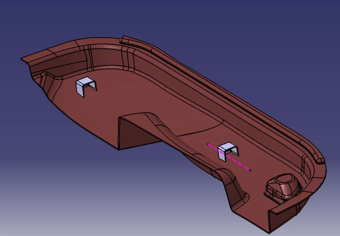
STEP 7 - Creation of Dog House over shown approximate location and as per design rules -
i.e. 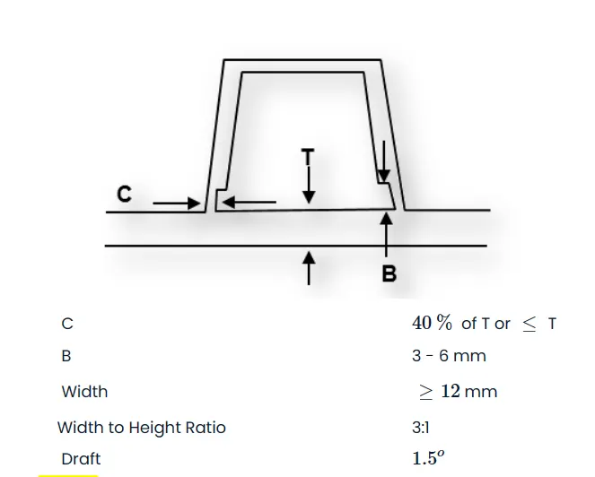
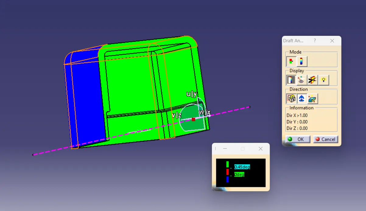
STEP 8 :- Draft analysis of final solid -
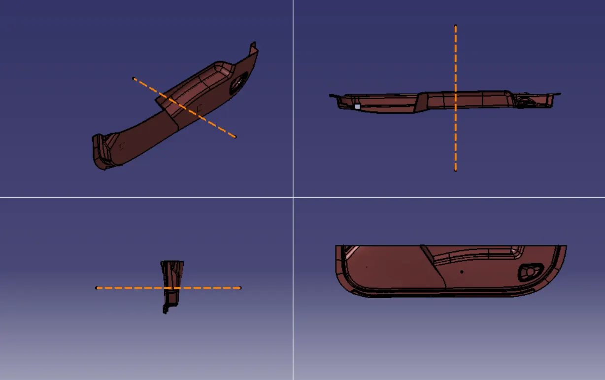
Screen shot of final body in all view -
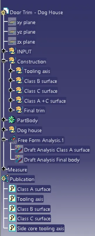
Screenshot of tree structure is attatched below here -
The CATPart file of above solution is attatched below.