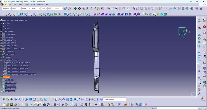
Week 10 - Challenge 2- Attachment Feature Creation (Dog House)
REPORT :
- Aim : To create a Door Trim Plastic Component through a given Class A Surface and perform Draft Analysis on the final plastic component.
-
Objectives :
- Creation of Tooling Axis.
- Creation of Class B and Class C surface.
- Creating a solid part out of surface modelling.
- Draft Analysis of Class A surface and final plastic component.
- Introduction : In this project we are designing a Door Trim using given Class A surface. The approach includes creation of Class B surface keeping 2.5 mm thickness in mind for the complete component. The design also included Class C creation from the given parent surface.
Constraints :
- NO CHANGES IN CLASS A ARE ALLOWED (BUT CLASS A & CLASS C SURFACE JOIN CREATE OPEN BOUNDARY, SO I HAVE TO EXLAPORATE CLASS A & TRIM WITH CLASS C).
- ALL DESIGN RULES SHOULD BE STRICTLY FOLLOWED.
- ALL SURFACES SHOULD BE CLOSED BEFORE CONVERTING TO SOLID.
- ALL FACES SHOULD MEET THE ALLOWED DRAFT REQUIREMENTS.
CLASS A : Following surface is given as the input for the component creation.
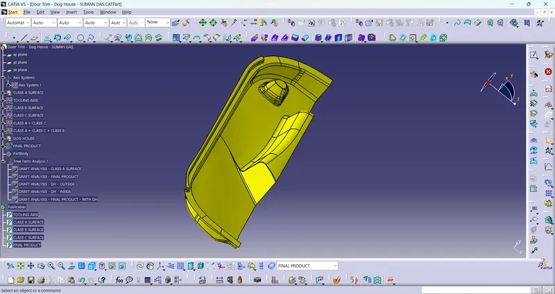
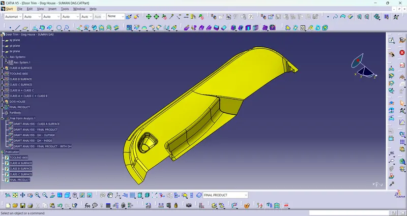
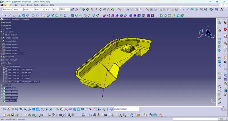
- Creation of Tooling Axis : The tooling axis is not created with bisecting method because of the complex geometry of Class A Surface. The dummy tooling axis is considered as main Tooling Axis.
-
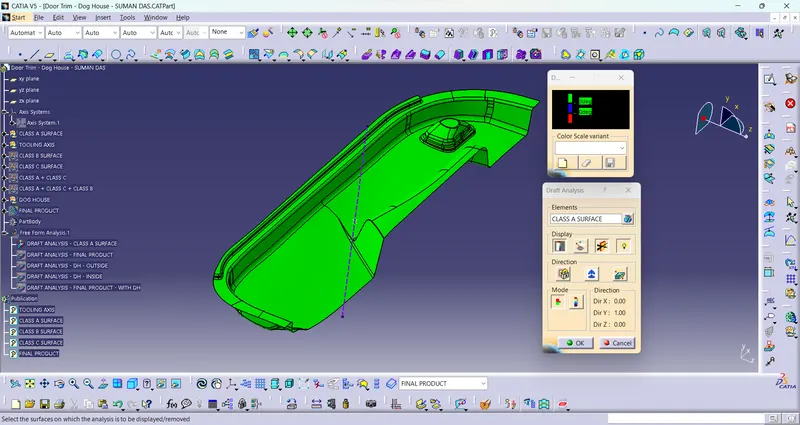
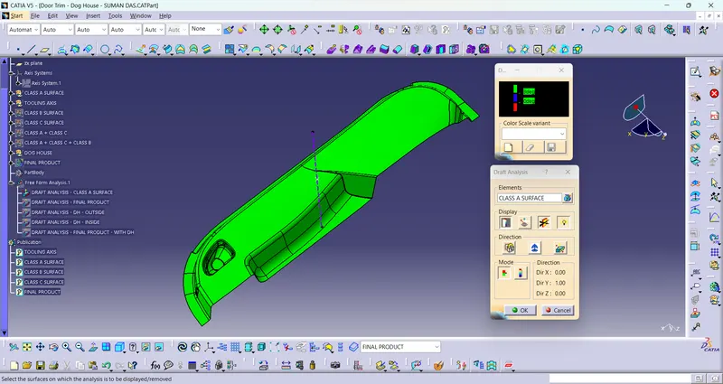
Draft Analysis for Surface A : The analysis is done for 3degree draft. So as can be seen all the surfaces are more than 3deg.
-
Creation of Class B :
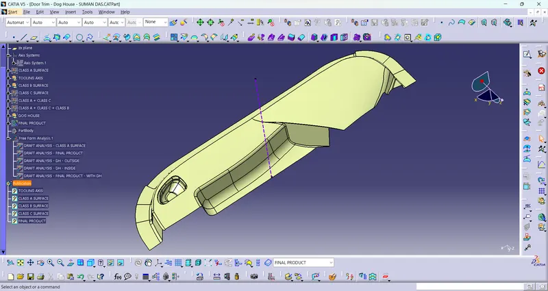
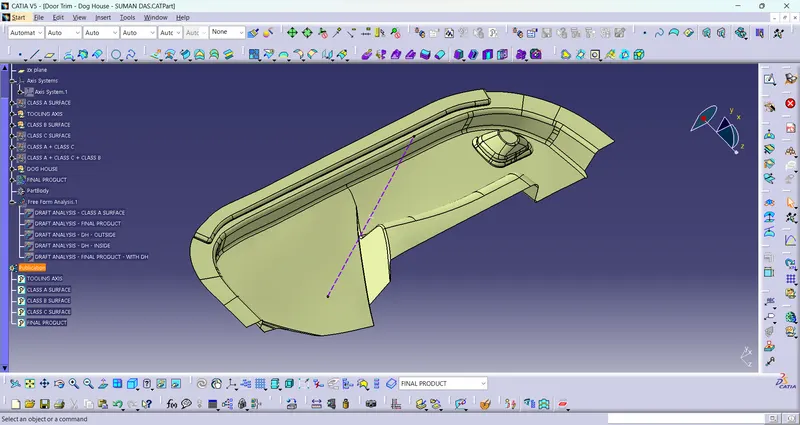
- Now for Class B creation, we have extracted surface from Class A and untrimmed them to obtain the original parent surface.
- These surfaces are then offset to the required thickness.
- After offsetting, all the surfaces are trimmed into the required shape.
- Required fillets are given to the surfaces.
-
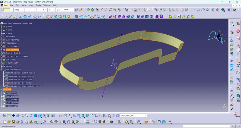
Creation of Class C surface :
- For creating this surface we have extracted the boundry of Class A using multi-extract and then converted to smooth curve.
- Now this smooth curve is swept along the draft direction with a 3deg draft.
-
Final Product :
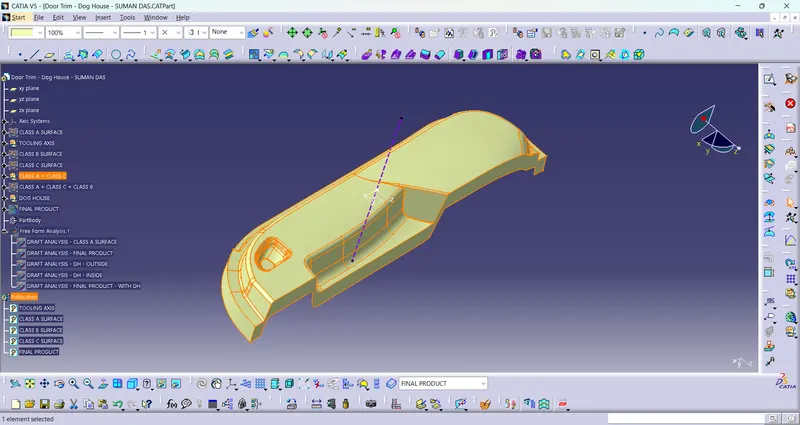
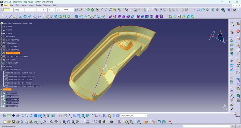
Class A + Class C :
To make sure that there is not any open boundry between class A and class C, we have used join option to created the single body. This is done to make sure that the parting line doesn't lie between the these two surfaces.
-
Class A + Class B + Class C :
For this we have trimmed the above shown surface with the Class B surface using trim feature.
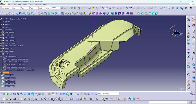
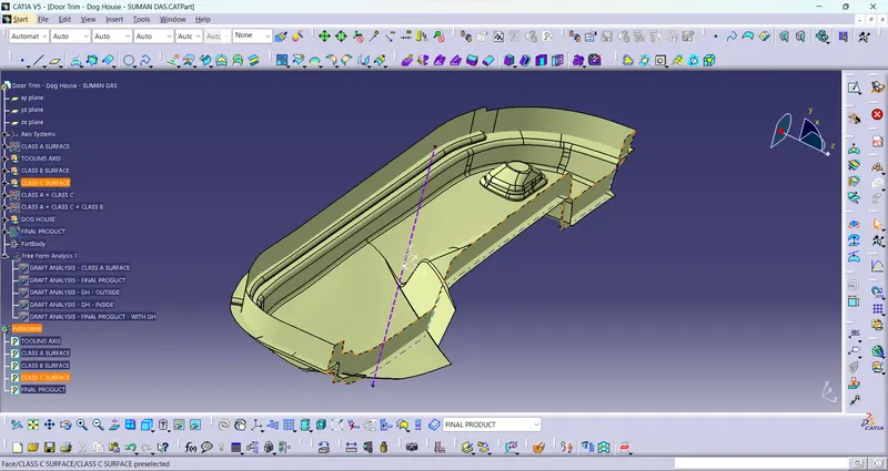
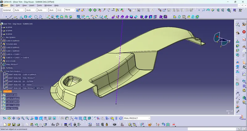
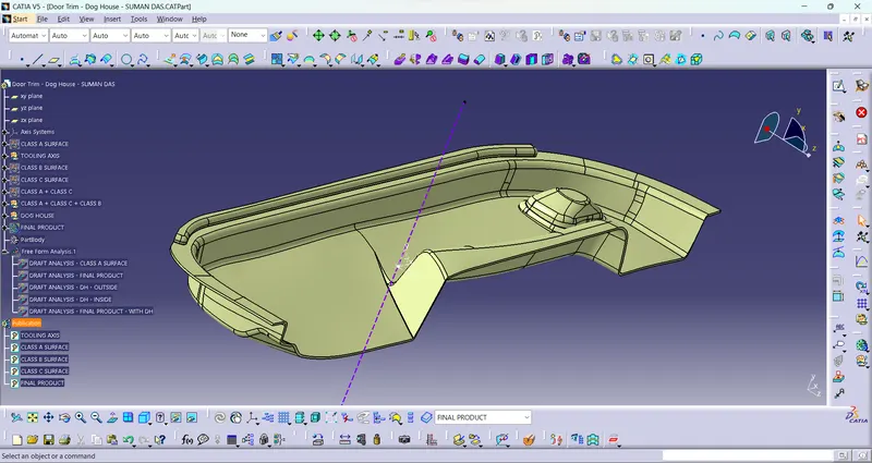
All the main features are published as can be seen in the image shown above.
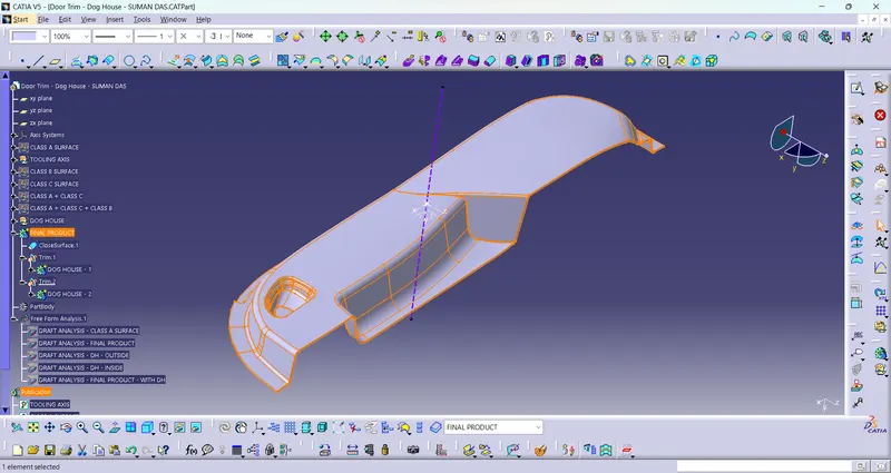
- Close Surface : We perform a close surface operaration to ensure that there is no open boundary of the final product of the Door Trim.
-
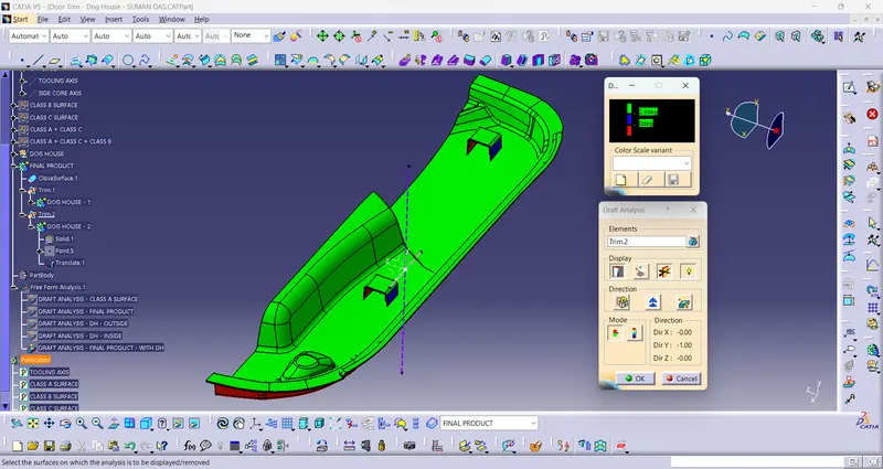
Draft Analysis on the Final Component : For this analysis, main tooling axis is taken draft reference. Following results were obtained.
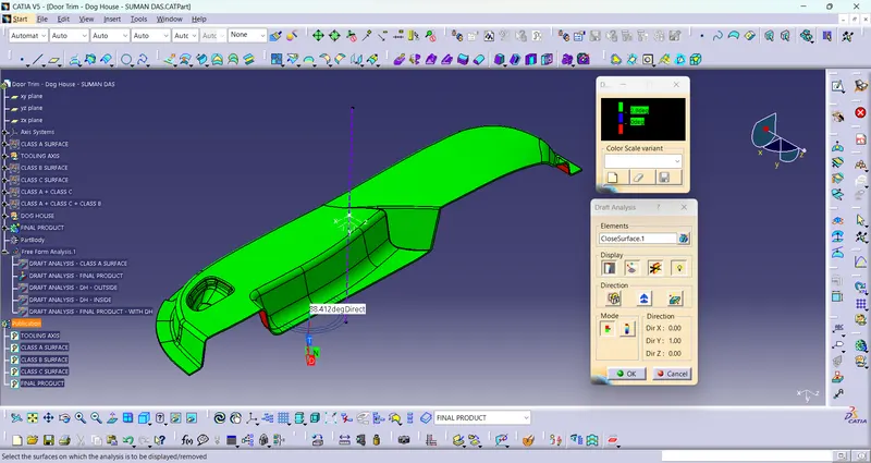
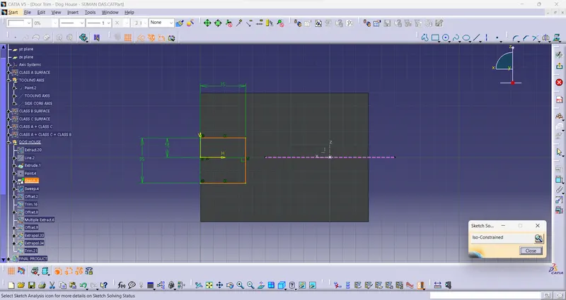
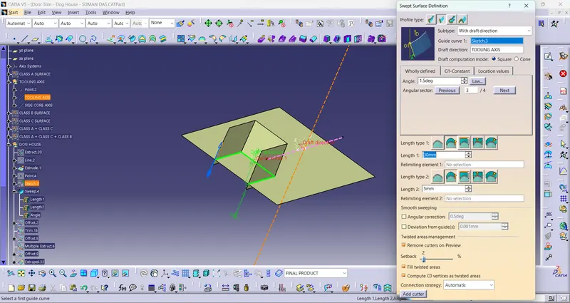
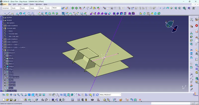
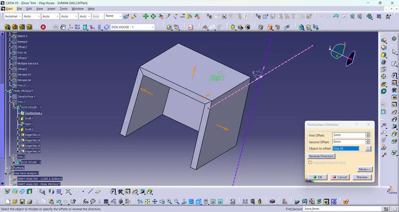
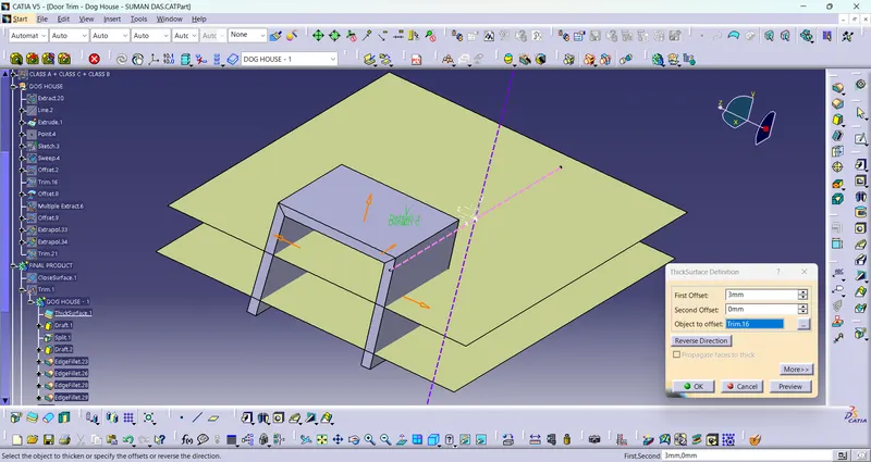
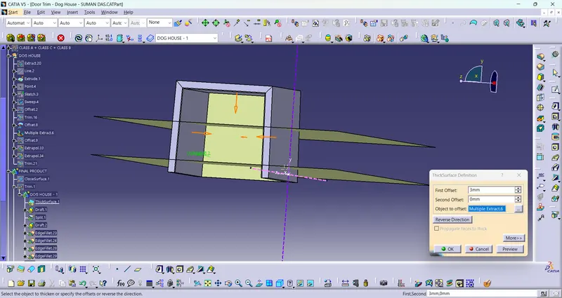
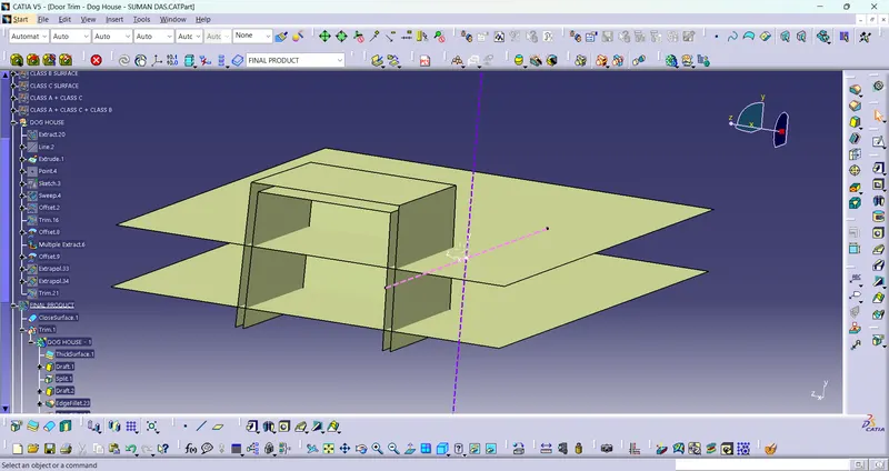
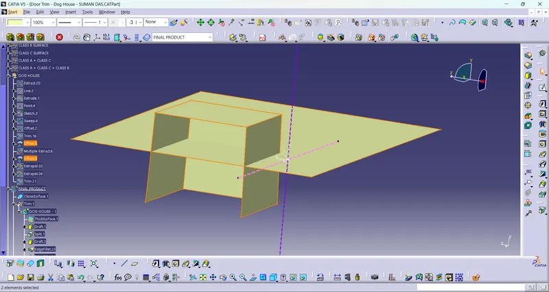
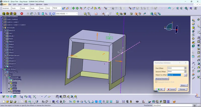
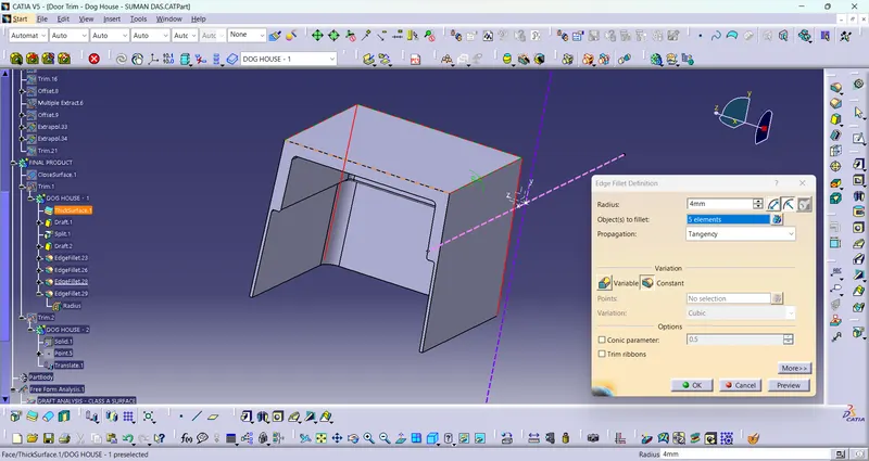
- DOG HOUSE DESIGN : First I create Side Core Axis at X direction. Then I create a straight plane with the referrence of XZ plane & extrude it. Then draw a 3 sided square on the plane. Then sweep the sketch with 1.5 degree draft direction. Then offset the plane & trim it with sweep for the upper surface of dog House.Then do the thicksurface operation with 3mm thickness. Then again do draft operation for inside surface of Dog House of 0.5 degree with Side Core Axis. Then again offset the sraight surface to do the "C" & "B" part of Dog House. Also multiple extract of the inside surface of the Dog House & trim it with the offset surface. Then split it with the thicksurface of Dog House to get "C" & "B" part of Dog House. Then untrim it with the main body. Then copy the Dog House & paste special it at main part. then create a point on another surface & translate the Dog House by point-point method. Then do the untrim operation again of translated Dog House with main body.
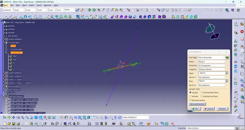
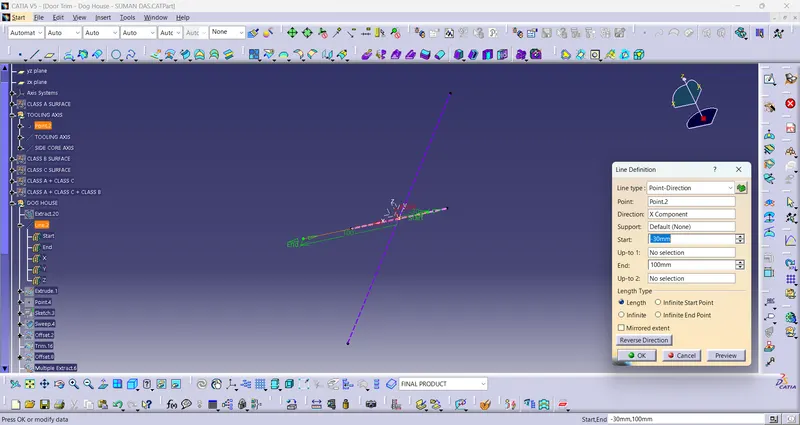
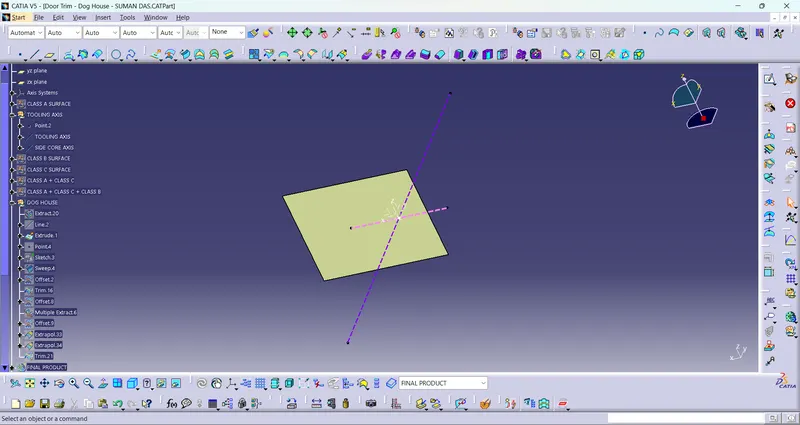
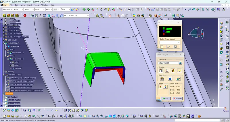
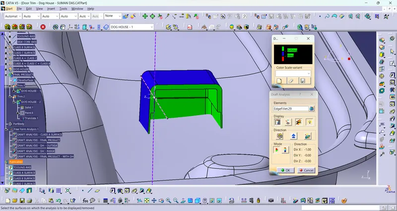
- Draft Analysis on the Dog House : For this analysis, main tooling axis is taken draft reference for outside surface analysis & side core axis is taken for inside surface analysis. Following results were obtained.
- Draft Analysis on the Final Component with Dog House : For this analysis, main tooling axis is taken draft reference. Following results were obtained.
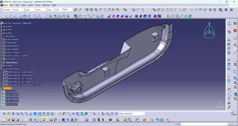
- ISOMETRIC VIEW :
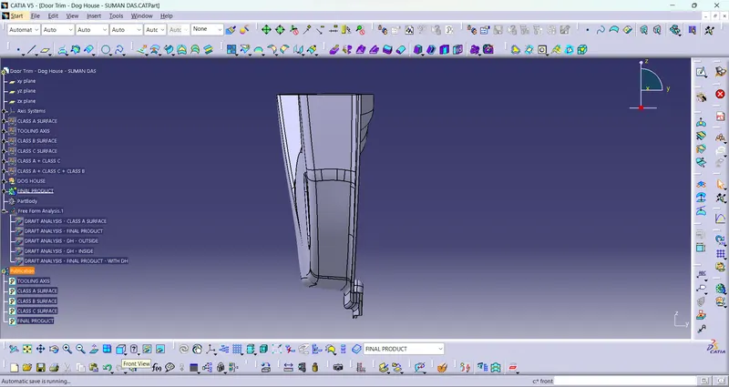
- FRONT VIEW :
- SIDE VIEW :
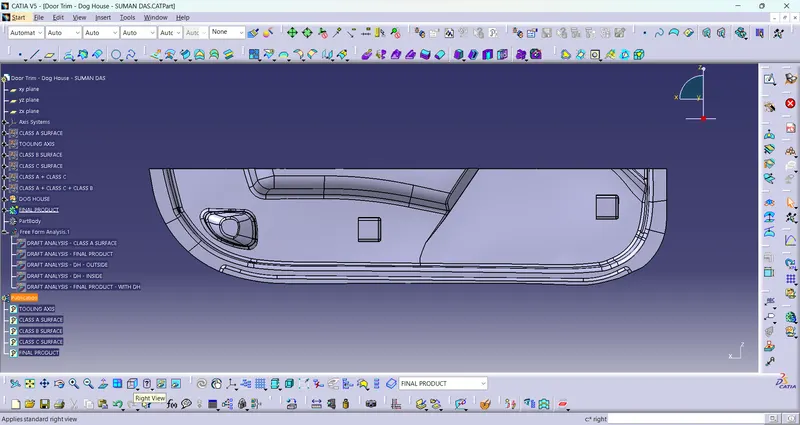
- TOP VIEW :