Week 10 - Challenge 2- Attachment Feature Creation (Dog House)
DOOR TRIM DESIGN
Attachment Feature Creation
(Dog House Addition)
- Objective: -
- Create the Door Trim & attachment features like dog house creation on the plastic component through the given Class-A surface.
- To begin with, the proper tooling axis for the given Class-A Surface should be created meeting the requirements of the draft angle and at the end perform the Draft analysis on the model.
- The inner panel is subjected to the draft analysis to ensure whether it is satisfying the deep drawing requirements for the tooling direction that is created in the design.
- Perform the draft analysis for each component & reinforcement.
- Introduction: -
Product design starts with requirements. The designer will sketch the product based on your requirements. He then uses advanced CAD software to transform the 2D sketch into his 3D model with proper dimensions. Another important aspect of design is that any designed product is manufacturable.
Therefore, the designer's role is to design products that are easy and inexpensive to manufacture.
This is where Design for Manufacturing [DFM] and Design for Assembly [DFA] play an important role in product development.
The design development process continues until the design meets the customer's requirements.
The Types of finishes and what they mean for automotive plastics designers:
Class A Surface: Class A is an aesthetic finish with the highest quality finish. Most Class A surfaces for automotive components are created using Autodesk Alias based on final concept sketches. All Class A surfaces must have "curvature continuity". That is, continuity between surfaces must have the same boundaries. It is used as a reference for automotive plastics designers to create "Class B" and "Class C" finishes.
Class B surface: A class B surface is below a class A surface at a certain thickness. It is created using structural principles consisting of all necessary features such as ribs, bosses and snaps. This surface is invisible to an outside observer.
Class C surface: A class C surface is a surface created to connect class A and class B surfaces.
Now, we will begin by checking the State of Connectivity for the Class A Surface and ensure that there are no gaps between the surfaces as all the surfaces should be joined well together with each other and shouldn't consist of any discontinuities between them.
By using the 'Boundary' Command' from the Operations Toolbar:
In this case, we have to click on the 'Boundary' command and then select the Class-A Surface. After that, we'll click on the 'Preview' button to highlight all the boundaries that are on the Class-A surface and check if there are any internal boundaries other than the outer edge boundaries.
TOOLING AXIS INTRODUCTION:
The direction in which the mould or core and cavity open is the tool axis. To easily visualize all openings, create boundaries or just use the connectivity option to see the connectivity of the surfaces. Visually analyse the optimal tool axis.
The Tooling Direction is the direction that the mould pulls apart. The mould is built in two separate pieces,
A Cavity side and The Core side.
The Core pulls apart from the Cavity and that's the Dyeline or the Tooling Direction. The direction in which the mould or core and cavity open is the tooling axis.
Features of the Tool:
Cavity half – The cavity half is the side of a tool that does not move. It is typically attached to the side of the moulding machine.
Core half – The side of the tool that opens and closes with the moulding machine against the cavity half. It opens when removing the part from the tool.
Cooling lines – Channels that allow coolant to flow throughout the tool and control the cooling of the plastic part.
Ejector system – Pins on the core half of the tool that helps push the cooled part out after moulding.
Runner – A flow path for the plastic resin allowing the press to inject material directly into the part cavity.
Side actions – Moving pieces within the part cavity added to allow for undercuts.
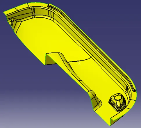
Tooling axis creation procedure: -
- First we performs a connectivity check to see if the given class A surface is It seems that there are no discontinuous boundaries.
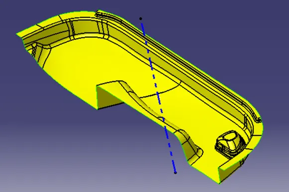
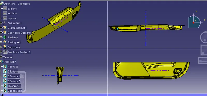
- Create extract of largest plane surface available. Create point on it with “0” distance. Then create line though “Point-Direction” option w.r.t. Y axis as it’s the axis which clears all of the surfaces.
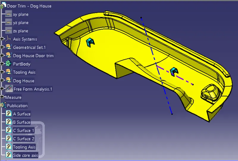
Main Tooling axis
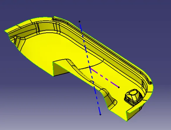
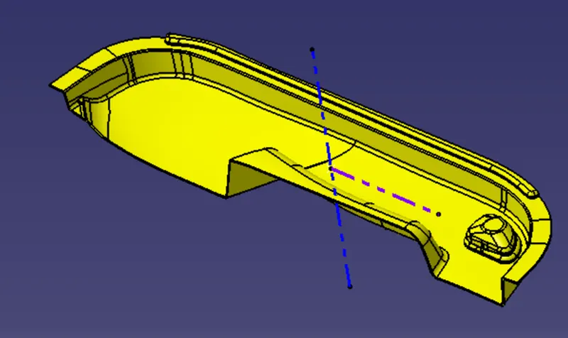
Side Core Axis for dog house (Purple Coloured)
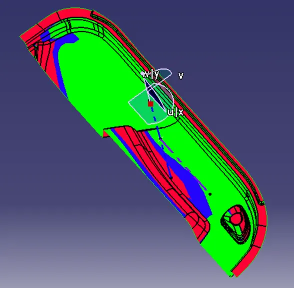
Design analysis of a Class A surface using the main tool axis:
Before starting a design analysis, go to the Tune View Parameters option on the View Toolbar. Then go to "Customize View Mode" under the "Mesh" option, select "Material" and press "OK". To start design analysis in the Generative Surface Design Workbench, go to Insert and look for the Analysis option.
Once you find it, go under it and click Feature Draft Analysis. This will open the Draft Analysis dialog box. So, under Mode, make sure Quick Analysis is selected, under Display, select Show or hide colour scale, and select 3 degrees as the allowable draft angle. Select. Then, under Direction, select the icon with the compass symbol that says "Use compass to define new current draft direction.
PROCEDURE OF BASE BRACKET DESIGN:
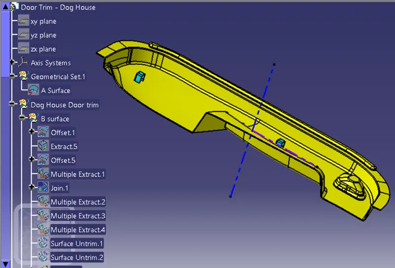
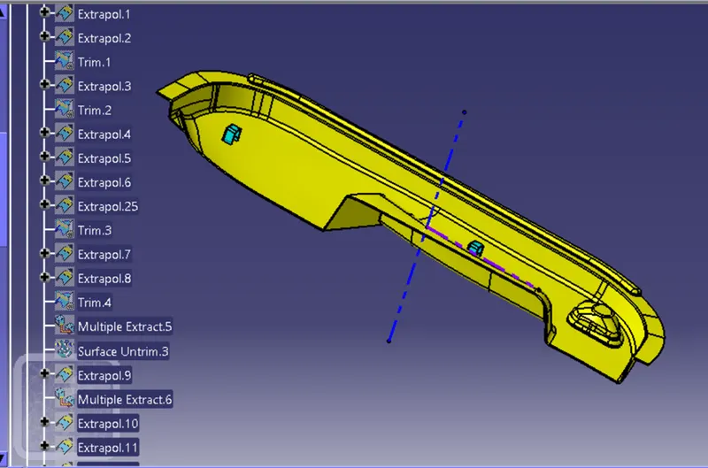
- B Surface Creation
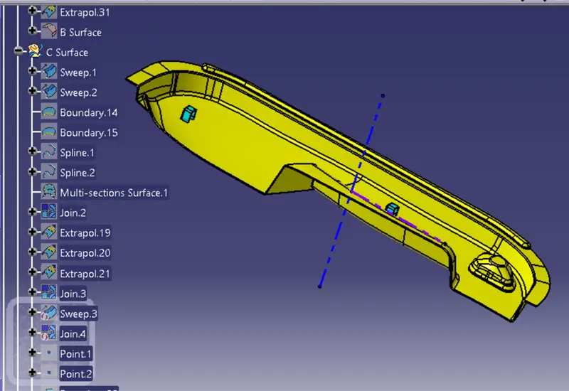
- C Surface Creation
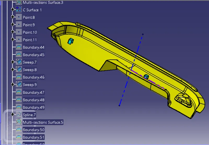
- Trim C-A & then B surface formed complete base bracket in surface
- Use closed surface command to convert into thick solid
B Surface Creation:
Start the process by creating an offset at a distance of 2.5 mm across the Class A surface. Because this is the desired thickness of the final plastic component. So since this is a complex surface the offset will not offset each element as needed. Some sub-elements are selected. These belong to rounded areas that need to be removed to get the remaining offset surface. This warning appears when trying to level a class A surface.
These "sub-elements" themselves are selected and deleted if you want to keep the rest of the offset surface.
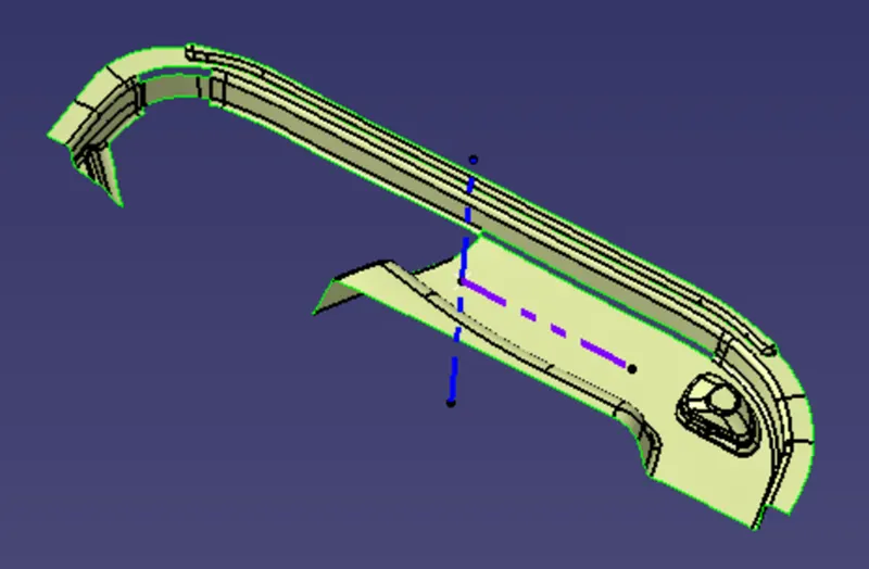
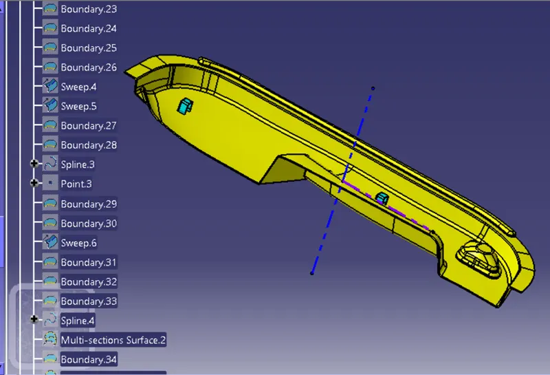
To fix all these patches, now use the create boundary & then MSS or Fill command. Select that boundary and click OK.
Then extract those patchy areas separately for extrapolate & the trim to form continuous surface/edges, Then use appropriate fillet to complete the B surface.
Again do extrapolate B surface to every open boundary which help to trim with C surface.
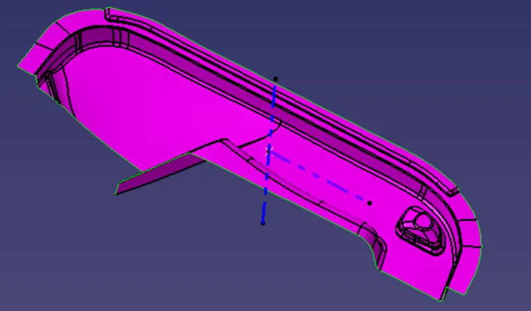
CLASS-C SURFACE creation:
This is the interface for class A and class B surfaces. Create a class-A surface boundary using the Boundary command. Use the Sweep command to create a Class C surface along the draft direction with a draft angle of 3 degrees to the tooling axis.
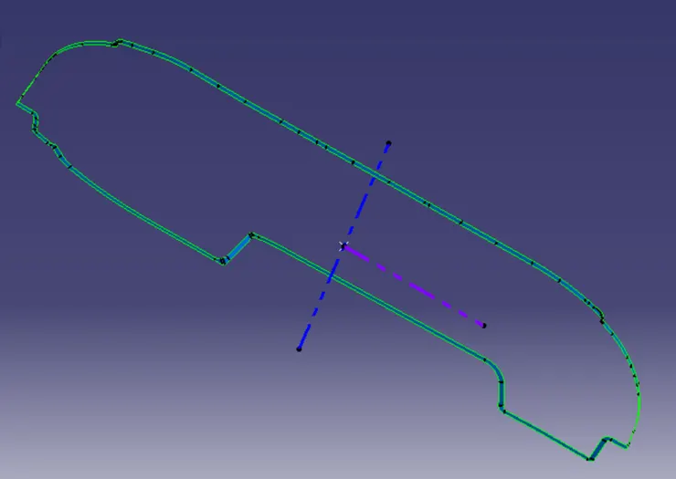
Use the Sweep command to create a Class C surface along the reference surface with an angle of 90 degrees to reference surface.
CLOSED SURFACE creation:
- Publish class-A, class-B, class-C surfaces and tooling axis.
- Join all the surface together.
- Create closed surface.
Trim Class-A & Class-C surface first then trim it with Class-B surface would form complete Base bracket.
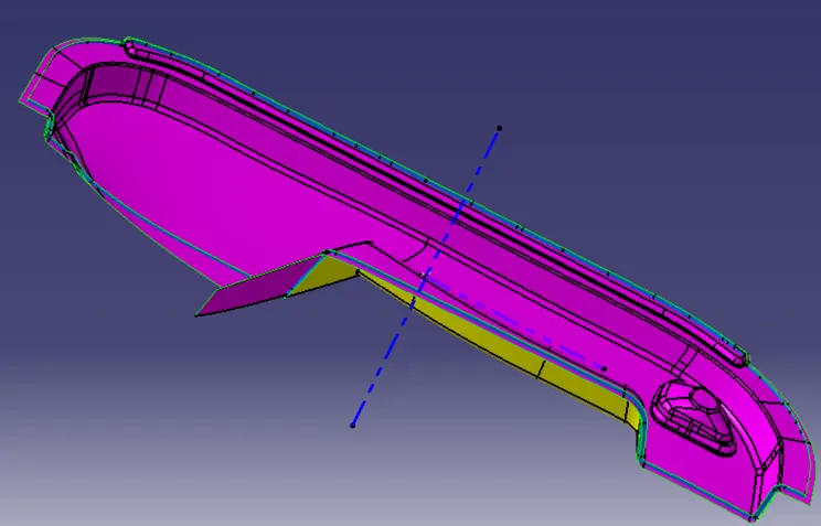
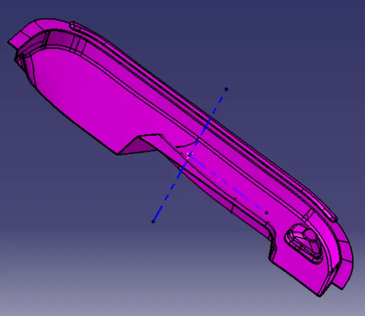
Solid Body creation:
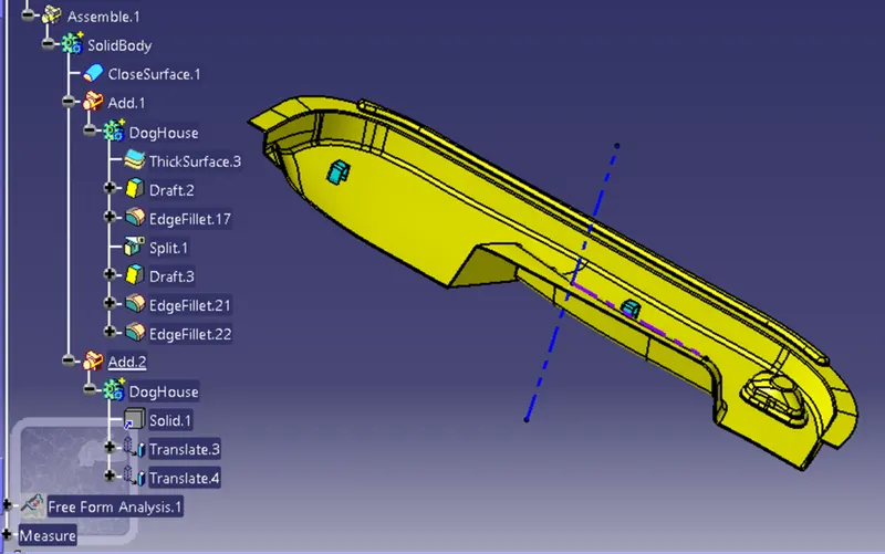
Now to create the solid body I used the closed surface command in the part workbench. Click on the closed surface command in the part workbench and give the closed surface as an input to create the solid part body.
Creating Solid body:
To create the solid body I used the closed surface command in the part workbench. Click on the closed surface command in the part workbench and give the closed surface as an input to create the solid part body.
Solid Body:
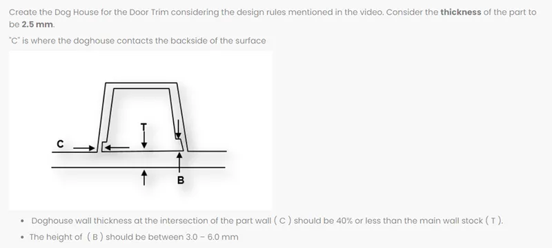
General Guidelines for Dog House:
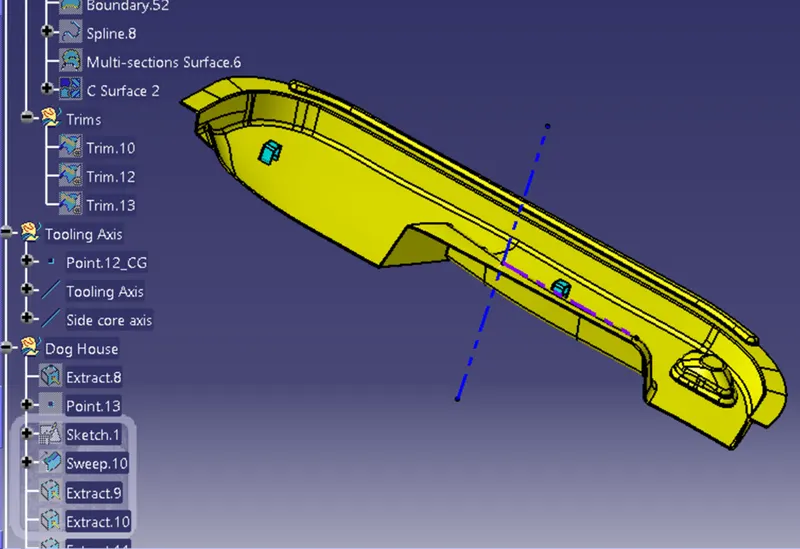
Dog House Creation:
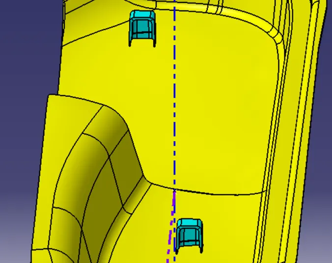
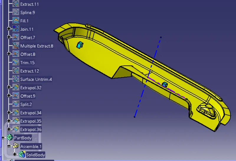
To design the Dog house, I made a sketch of the Dog house. First, I created a plane on the class B surface at "Point.1". After drawing the sketch, sweep the sketch up 20mm and down 1mm (to blend properly with the part body) with a draft angle of 1.5 degrees and thicken the surface outwards by 2mm.
Next, we need to design the bottom connection of the Dog house. To design the bottom link of the Dog house, I extracted the inside surface and offset it 1mm to the outside. Offset the top cut-out 13mm down and trim with a 1mm offset face.
Use Part Workbench's Split command to split the solid using the trimmed surface. Here we have specified a draft angle of 0.5 degrees for the split plane. The inner gap area is 0.5mm, the inner fillet is 1mm and the outer fillet is 3mm (inner fillet 1mm + thickness 2mm = outer fillet 3mm).
Design analysis of the finished product using the main tool axis:
Click Design Analysis under the Analysis toolbar in Part Workbench. Then click the compass icon under "Direction" which stands for "Use the compass to define the new current draft direction".
Drag the compass to place it on the main tool axis. Then select Show or hide colour scale under Display and define a draft angle of 3 degrees. Because this component was created from a Class A trimmed surface, you do not need to specify draft for each area. I specified 3 degrees of draft for all the surfaces I needed.
Then click the surface of the last part. Here are the result:
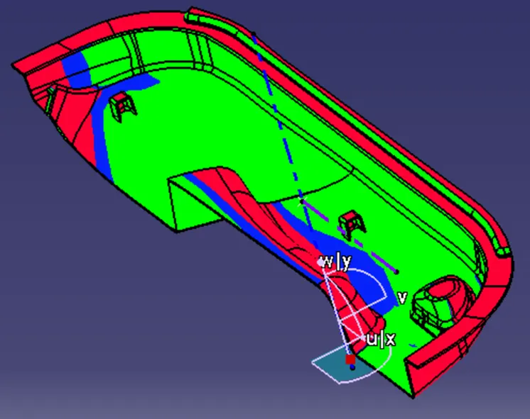
Limiting draft angle = 3 degrees
Draft analysis from the selected tooling axis location.

- Conclusion: -
The Door Trim with dog house Design is completed w.r.t Class-A surfaces & draft analysis also done completely with the help of CATIA software.