Week 10 Challenge
Question:
1)What all checks need to be followed in design of well foundation regarding the stability and the design. List out all the necessary clauses from IRC codes applicable.
What are the limits in ULS and SLS for design of a RCC component. Define the limit states and the factors in it as per IRC 112.
Also mention shear checks. what is the difference in shear with/without reinforcement?
How to check steining thickness and its steel.
What will be the change in PCC and RCC steining.
1. How the spacing of pile is determined in 6 pile system . describe the bulb theory with neat diagrams showing the stress distributions.
Driven cast in situ piles can be assumed. You are free to choose the depth, number, and diameter of the pile. give reactions of at least two different piles (assuming different pile dias)
Assume spacing as 3 times diameter.
Lateral load to be equally shared by all piles. Vertical capacity as 2000 KN for 1.2 m 1750 kn for 1 m 1500 kn for 0.9 m pile diameter.
Question:
1)What all checks need to be followed in design of well foundation regarding the stability and the design. List out all the necessary clauses from IRC codes applicable.
Designing a well foundation for stability and safety requires careful consideration of various factors to ensure its structural integrity. The specific requirements and codes can vary by region and project.
We should be taken some general guidelines and common checks based on Indian Road Congress (IRC) codes, which are often used for well foundation design in India.
Here are some important checks and clauses to consider:
<!-- [if !supportLists]-->1. <!--[endif]-->Geotechnical Investigation (IRC: 78-2014):
Conduct a thorough geotechnical investigation to determine soil properties, including bearing capacity, soil strata, and groundwater levels.
<!-- [if !supportLists]-->2. <!--[endif]-->Foundation Size and Shape (IRC: 78-2014):
Select an appropriate shape and size for the well foundation based on the load and soil conditions.
Ensure that the well is deep enough to reach competent strata to support the loads.
<!-- [if !supportLists]-->3. <!--[endif]-->Bearing Capacity (IRC: 78-2014):
Calculate the allowable bearing capacity of the soil and ensure that it exceeds the applied loads.
<!-- [if !supportLists]-->4. <!--[endif]-->Settlement Analysis (IRC: 78-2014):
Perform settlement analysis to ensure that the foundation settlement is within permissible limits.
<!-- [if !supportLists]-->5. <!--[endif]-->Stability Analysis (IRC: 78-2014):
Check the stability of the well foundation under various loading conditions, including vertical and lateral loads.
<!-- [if !supportLists]-->6. <!--[endif]-->Design of Well Cap (IRC: 78-2014):
Design the well cap to distribute the load uniformly to the well shaft.
Consider the use of reinforcing bars and concrete to enhance the well cap's strength.
<!-- [if !supportLists]-->7. <!--[endif]-->Well Lining (IRC: 78-2014):
Design the well lining to resist buoyancy, uplift forces, and lateral pressures from surrounding soil and water.
<!-- [if !supportLists]-->8. <!--[endif]-->Seepage Control (IRC: 78-2014):
Incorporate measures to control seepage through the well foundation, such as grouting or providing a cut-off wall.
<!-- [if !supportLists]-->9. <!--[endif]-->Material Specifications (IRC: 78-2014):
Ensure that the materials used for construction meet the specified standards and requirements.
<!-- [if !supportLists]-->10. <!--[endif]-->Construction Quality Control (IRC: 78-2014):
Implement a quality control program during construction to monitor compliance with design specifications.
<!-- [if !supportLists]-->11. <!--[endif]-->Load Testing (IRC: 78-2014):
Conduct load tests to validate the design assumptions and performance of the well foundation.
<!-- [if !supportLists]-->12. <!--[endif]-->Environmental Considerations (IRC: 78-2014):
Consider the impact of the well foundation on the environment, especially in terms of water flow and aquatic life.
<!-- [if !supportLists]-->13. <!--[endif]-->Safety Measures (IRC: 78-2014):
Implement safety measures during construction and maintenance to prevent accidents and ensure worker safety.
<!-- [if !supportLists]-->14. <!--[endif]-->Documentation and Record-Keeping (IRC: 78-2014):
Maintain detailed records of the design, construction, and inspection of the well foundation.
Question:
<!-- [if !supportLists]-->15. <!--[endif]-->What are the limits in ULS and SLS for design of a RCC component. Define the limit states and the factors in it as per IRC 112.
In the context of reinforced concrete (RCC) design in accordance with the Indian Roads Congress (IRC) guidelines, Ultimate Limit State (ULS) and Serviceability Limit State (SLS) are critical considerations.
These limit states help ensure the safety and functionality of RCC components. The limit states, the factors involved, and discuss shear checks, including the difference in shear with and without reinforcement.
<!-- [if !supportLists]-->1. <!--[endif]-->Ultimate Limit State (ULS):
The ULS is concerned with ensuring the structural safety of the RCC component under extreme loading conditions. It involves assessing whether the component can withstand the maximum loads without collapsing. In the context of IRC 112, the following factors are considered:
<!-- [if !supportLists]-->a. <!--[endif]-->Materials Factor: (As per IRC:112-2020, A2.10)
This involves checking if the concrete and reinforcement can resist the applied loads. Material properties, such as the characteristic strength of concrete and steel, are critical factors.
For Materials
Material Basic Comb Seismic Comb
Concrete 1.5 1.5
Reinforcing Steel 1.15 1.15
<!-- [if !supportLists]-->b. <!--[endif]-->Design Load Factors:( IRC:06-2017, Table B.2)
These factors account for uncertainties in loadings and material properties. Load factors are applied to different types of loads, such as dead loads, live loads, and wind loads, to determine the design loads etc.
Load Basic Seismic Combination Combination
<!-- [if !supportLists]-->1. <!--[endif]-->Deal Load 1.35 1.35
<!-- [if !supportLists]-->2. <!--[endif]-->SIDL except Surface 1.35 1.35
<!-- [if !supportLists]-->3. <!--[endif]-->SIDL Surface 1.75 1.75
<!-- [if !supportLists]-->4. <!--[endif]-->Live load & Associated Loads-
(Leading) 1.5 0
<!-- [if !supportLists]-->5. <!--[endif]-->Live load & Associated Loads-
(Accompanying) 1.15 0.2
<!-- [if !supportLists]-->6. <!--[endif]-->Water Current 1 1
<!-- [if !supportLists]-->7. <!--[endif]-->Buoyancy 0.15 0.15
<!-- [if !supportLists]-->8. <!--[endif]-->Earth Pressure 1.5 1.0
<!-- [if !supportLists]-->9. <!--[endif]-->Live load surcharge 1.2 0.2
<!-- [if !supportLists]-->10. <!--[endif]-->Seismic Effect (During Service) 1.5
<!-- [if !supportLists]-->11. <!--[endif]-->Seismic Effect- (During Constructions) 0.75
<!-- [if !supportLists]-->12. <!--[endif]-->Thermal loads-As leading 1.5 0.0
<!-- [if !supportLists]-->13. <!--[endif]-->Thermal loads-As Accompanying 0.9 0.5
<!-- [if !supportLists]-->14. <!--[endif]-->Live load Surcharges-As Accompanying 1.2 0.0
<!-- [if !supportLists]-->15. <!--[endif]-->Braking Force-As leading 1.5 0.0
<!-- [if !supportLists]-->16. <!--[endif]-->Braking Force- As Accompanying 1.15 0.2
<!-- [if !supportLists]-->2. <!--[endif]-->Serviceability Limit State (SLS):
The SLS focuses on ensuring the functionality and durability of the RCC component throughout its service life.
IRC 112 considers the following factors:
<!-- [if !supportLists]-->a. <!--[endif]--> Deflection:
Assessing whether the component deflects within acceptable limits under service loads. Excessive deflection can affect the functionality and appearance of the structure.
<!-- [if !supportLists]-->b. <!--[endif]-->Cracking:
Checking for the formation and width of cracks in the concrete. IRC 112 specifies limits on crack widths to ensure durability and corrosion protection of reinforcement.
<!-- [if !supportLists]-->c. <!--[endif]-->Long-Term Effects:
Considering long-term effects such as creep and shrinkage of concrete, which can affect the behaviour of the structure over time.
<!-- [if !supportLists]-->3. <!--[endif]-->Also mention shear checks. what is the difference in shear with/without reinforcement?
<!-- [if !supportLists]-->a. <!--[endif]-->Shear Checks:
Shear checks are essential in RCC design to ensure that the component can resist shear forces. Shear is the force that acts parallel to the surface of a structural member, trying to cause it to slide apart.
The difference in shear behaviour with and without reinforcement is significant:
<!-- [if !supportLists]-->a. <!--[endif]-->Shear without Reinforcement:
In an unreinforced concrete component, shear strength primarily relies on the inherent resistance of concrete to shear forces. The concrete must be designed to have sufficient shear strength to resist the applied shear loads.
b. Shear with Reinforcement:
In reinforced concrete, shear reinforcement, such as stirrups or shear links, is added to enhance shear capacity. The reinforcement provides additional resistance to shear forces, preventing premature shear failure.
The choice of shear reinforcement type and spacing depends on the specific design requirements and loadings. Proper detailing and spacing of shear reinforcement elements are crucial to ensuring the structural integrity of the component under shear forces.
<!-- [if !supportLists]-->· <!--[endif]-->Conclusion:
IRC 112 outlines the design considerations for ULS and SLS in RCC components, with a focus on factors such as material strength, load factors, safety factors, deflection, cracking, and long-term effects.
Shear checks are important for assessing shear capacity, and the presence of reinforcement significantly improves shear resistance in reinforced concrete components compared to unreinforced ones.
Question:
How to check steining thickness and its steel.
Answer:
Steining of Well Foundation:
Steining is a wall or shall type of structure made up of RCC, and which helps to transfer the load to the curb. It serves as an enclosure for excavating the soil for the penetration of the foundation well.
It shall be considered as a column section subjected to combined axial load and bending.
Thickness of steining of well: As per IRC:78-2014, Clause No.708.2.3.1
The Minimum Thickness of the well steining shall not be less than 500mm and satisfy the following relationship has given below:

Where,
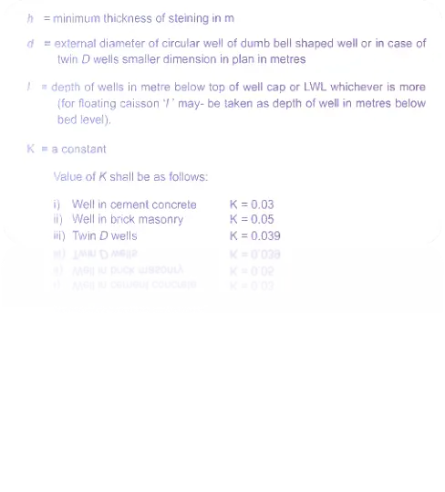
We should be considered to check thickness of steining of well foundation as per above equation according to IRC:78-2014 guidelines.
Reinforcement of Steining: As per IRC:78-2014, Clause No.708.3.4
Will provide the reinforcement in the straining of well foundation as per given clause.
The amount of vertical reinforcement provided in the staining shall not be less than 0 .2% of the actual gross sectional area of the straining.
The minimum reinforcement of the staining inner face is 0 .06% of the gross cross-sectional area of this staining.
The transverse reinforcement in the staining shall be provided in accordance with the provision for a column but in no case shall be less than, 0 .04% of the volume per unit length of the staining.
Reinforcement of the Staining: As per IRC:78-2014, Clause No.708.3.4
feel
Vertical- Outer Face = 0.20%
Vertical- Inner Face = 0.06%
Transverse = 0.04%
Question:
What will be the change in PCC and RCC steining.
Answer:
Differences between PCC and RCC:
<!-- [if !supportLists]-->· <!--[endif]-->Purpose:
PCC is primarily used as a non-structural layer which shall be provided in well steining more thickness corresponding to RCC steining, so self-weight is more than RCC. RCC, on the other hand, is used for structural elements that bear loads.
<!-- [if !supportLists]-->· <!--[endif]-->Reinforcement:
PCC typically does not contain steel reinforcement, while RCC always includes steel reinforcement bars to enhance its strength and ductility.
<!-- [if !supportLists]-->· <!--[endif]-->Strength:
RCC has a higher compressive and tensile strength compared to PCC, making it suitable for structural applications.
<!-- [if !supportLists]-->· <!--[endif]-->Thickness:
PCC is generally thinner and used as a base layer, while RCC elements vary in thickness based on their structural requirements.
<!-- [if !supportLists]-->· <!--[endif]-->Load bearing:
RCC is designed to bear structural loads such as live loads and dead loads, whereas PCC is not designed for load-bearing purposes.