Week 10 Challenge
1) The design of well foundations for bridges and other structures involves various checks to ensure stability and safety. The specific clauses from the Indian Road Congress (IRC) code applicable to well foundation design can vary depending on the type of structure, soil conditions, and other factors.
Here are some of the key aspects and checks involved in the design of well foundations:
Load Calculation and Distribution:
- Determine the loads from the superstructure and other loads (live load, wind load, seismic load, etc.).
- Distribute the loads to the well cap and subsequently to the individual well caissons.
- Consider the eccentricities of loads and ensure the resultant force falls within the base area.
Bearing Capacity of Soil:
- Calculate the ultimate bearing capacity of the soil at the site using relevant soil parameters.
- Verify that the applied loads are within the safe bearing capacity of the soil.
Settlement Analysis:
- Analyze the settlement of the well foundation and ensure that it remains within acceptable limits.
- Consider both immediate and consolidation settlements.
1. Sliding Stability:
- Check for sliding stability by calculating the forces resisting sliding and comparing them with the sliding forces.
- Consider both horizontal and vertical directions.
2. Overturning Stability:
- Check for overturning stability by comparing the moment due to applied loads with the resisting moment provided by the soil's bearing capacity.
3. Scour Considerations:
- If the well foundation is in a river or water body, consider the potential for scour around the well foundation and provide suitable protection measures.
4. Lateral Stability:
- Evaluate the lateral stability of the well caissons against buckling.
- Provide suitable bracing or consider the effects of battering the caissons.
5. Seismic Design:
- Account for seismic loads as per the relevant seismic design code.
- Check the foundation's stability under seismic conditions.
6. IRC Codes:
- IRC SP 55: "Guidelines for the Design of Well Foundations" provides detailed guidelines for the design of well foundations for bridges.
- IRC 78: "Code of Practice for Design and Construction of Well Foundations" provides comprehensive information on various aspects of well foundation design.
All the checks are considered from the IRC 78 codes.
- Clause 706.1 for Loads, Forces and their combination.
- Clause 706.2 for Horizontal Forces at Bearing Level.
- Clause 706.3 for Base pressure check
- Clause 706.3.1.1 for Factor of Safety.
- Clause 706.3.2.2 for Allowable settlement/differential settlement.
- Clause 706.3.3 for No tension shall be permitted under any combination of loads on the soil.
- Clause 706.3.4 for Factor of safety for stability.
- Clause 708.2 for Well stening design.
- Clause 708.5 for Tilts and shifts.
IRC 112, titled "Code of Practice for Concrete Road Bridges," outlines the design criteria for reinforced concrete components in road bridges. It defines various limit states and the associated factors of safety for the Ultimate Limit State (ULS) and Serviceability Limit State (SLS). Additionally, it provides guidelines for shear checks in concrete components. Here's an overview based on the information available as of my last update in September 2021:
Limit States and Factors of Safety:
1. Ultimate Limit State (ULS):
- Limit State: The Ultimate Limit State corresponds to the condition where the structure or a component reaches its ultimate capacity and cannot sustain any additional load without failure.
- Factors of Safety: IRC 112 specifies a partial safety factor for dead loads (γ_d), a partial safety factor for live loads (γ_l), and a partial safety factor for material strength (γ_m).
2. Serviceability Limit State (SLS):
- Limit State: Serviceability Limit State refers to the condition where the structure or a component maintains its functionality while not causing discomfort to users due to excessive deformations or vibrations.
- Factors of Safety: IRC 112 does not explicitly provide separate factors of safety for SLS. However, it's important to ensure that deformations and vibrations are within acceptable limits.
Shear Checks in Concrete Components:
IRC 112 provides guidelines for shear checks in concrete components based on the shear strength of the material. Shear checks are performed to ensure that the structure can resist the shear forces effectively and prevent shear failure.
Difference in Shear with/without Reinforcement:
The inclusion of shear reinforcement significantly enhances the shear capacity of concrete components. In reinforced concrete components, shear reinforcement (such as stirrups or shear links) is provided to improve the shear resistance of the structure.
-
Shear without Reinforcement: In plain concrete components, the shear strength is relatively lower. The concrete can fail suddenly and without warning in shear if not properly designed.
-
Shear with Reinforcement: Shear reinforcement, in the form of stirrups or links, enhances the shear capacity of concrete components. It prevents the shear failure of concrete by providing additional paths for distributing shear forces and resisting diagonal cracking. The reinforcement helps to ensure a more ductile failure mode, which gives occupants more time to react in case of overloading.
According to IRC:112-2020 following are the limits in ULS for the design of an RCC component.
Limit states (Ultimate limit state), Section 5
- Limit the state of equilibrium
- Limit state of strength.
Ultimate limit state of linear element for bending and axial forces, section 8.
- Strain and Stress Distribution at Ultimate Limit State.
- Biaxial Bending
Ultimate Limit State of Two and Three-Dimensional Elements for Out of Plane and in Plane Loading Effects, section 9.
Ultimate Limit State of Shear, Punching Shear and Torsion, section 10.
- Design of Flexural Members for Shear.
- Design for Punching Shear.
- Torsion.
Ultimate Limit State of Induced Deformation, section 11.
According to IRC:112-2020 following are the limits in SLS for the design of an RCC component.
Limit states (Serviceability limit state), Section 5
- Limit state of internal stress.
- Limit the state of crack control.
- Limit state of deformation.
- Limit state of vibration.
- Limit state of fatigue.
Serviceability limit state, section 5
- Stress Limitation.
- Limit State of Cracking.
- Limit State of Deflection.
The specific requirements for shear design, including the amount and spacing of shear reinforcement, are provided in IRC 112 and depend on factors such as the type of structure, loading conditions, and the concrete's compressive strength.
Checking Reinforced Concrete Element (Beam/Column) Thickness and Steel:
-
Understand Design Requirements: Before checking the thickness and steel of a structural element, you need to understand the design requirements, loadings, and other relevant parameters. This includes referring to the design codes and standards applicable to your region, such as the relevant sections of IRC 112 for Indian road bridges.
-
Gather Design Data: Collect all necessary design data, including the type of structure (beam, column, etc.), loading conditions, span lengths, support conditions, material properties, and any relevant design loads (dead loads, live loads, etc.).
-
Determine Member Dimensions: Based on the design requirements and loadings, calculate the required dimensions of the structural member, including its cross-sectional dimensions (width and depth) and any other geometrical considerations.
-
Check Thickness: Verify that the calculated thickness of the structural member (e.g., the depth of a beam or column) meets the minimum requirements set by the design code. This ensures that the member can resist the applied loads and provide adequate structural capacity.
-
Check Steel Reinforcement: Determine the required amount of steel reinforcement for the structural member based on the design loads and material properties. This involves calculating the area of steel required to resist bending, shear, and other relevant forces.
-
Verify Steel Quantity: Check the calculated steel quantity against the minimum and maximum steel ratios specified in the design code. Ensure that the provided steel is within the acceptable range to ensure both structural safety and constructability.
-
Check for Spacing and Cover Requirements: Ensure that the spacing of steel bars (both longitudinal and transverse) conforms to the code's guidelines. Also, check that the concrete cover over the reinforcement is sufficient to protect it from corrosion and provide fire resistance.
-
Detailing and Drawing Preparation: Based on the calculated steel requirements, prepare detailed reinforcement drawings that show the layout, diameter, spacing, and other details of the reinforcement bars within the structural element.
-
Review and Approval: Have the calculations, drawings, and specifications reviewed by a qualified structural engineer to ensure compliance with design codes and safety standards.
-
Quality Control During Construction: During construction, ensure that the actual thickness and reinforcement placement adhere to the design requirements. Regular inspections and quality control checks are essential to maintain the integrity of the structure.
PCC and RCC in structural components like foundation walls or other similar elements, here are the key differences:
PCC (Plain Cement Concrete):
Plain Cement Concrete, often referred to as PCC, is a simple mixture of cement, fine aggregates (sand), coarse aggregates (usually small stones or gravel), and water. It is used in construction for non-structural elements or as a base for laying other materials like bricks or tiles.
RCC (Reinforced Cement Concrete):
Reinforced Cement Concrete, or RCC, is a composite material that includes cement, aggregates, water, and reinforcement (usually steel bars). It's used in the construction of structural elements like beams, columns, slabs, and foundations.
Following are the calculation which is used to determine the steining thickness which is mentioned in IRC:78 clause no 708.2.3.1
Formula:- h=Kd
h = minimum thickness of steining in m
d = external diameter of the circular well of dumb bell shaped well or in the case of twin D wells smaller dimension in plan in metres
l = depth of wells in metre below the top of well cap or LWL whichever is more (for floating caisson 7 ' may- be taken as the depth of well in metres below bed level).
K = a constant.
The value of K shall be as follows:
- Well in cement concrete K = 0.03.
- Well in brick masonry K = 0.05.
- Twin D wells K = 0.039
Changes in PCC and RCC steining are given in IRC:78
- Clause 708.3.3 For plain concrete wells, vertical reinforcements (whether mild steel or deformed bars) in the steining shall not be less than 0.12 per cent of the gross sectional area of the actual thickness provided. This shall be equally distributed on both faces of the steining. The vertical reinforcements shall be tied up with hoop steel not less than 0.04 per cent of the volume per unit length of the steining.
- Clause 708.3.4 In case where the well steining is designed as a reinforced concrete element, it shall be considered as a column section subjected to combined axial load and bending. However, the amount of vertical reinforcement provided in the steining shall not be less than 0.2 per cent (for either mild steel or deformed bars) of the actual gross sectional area of the steining. On the inner face, a minimum of 0.06 per cent (of gross area) steel shall be provided. The transverse reinforcement in the steining shall be provided in accordance with the provisions for a column but in no case shall be less than 0.04 per cent of the volume per unit length of the steining.
Key Differences:
1. Reinforcement:
- PCC: Plain cement concrete does not contain any reinforcement. It relies solely on the properties of the concrete mix for strength and stability.
- RCC: Reinforcement is an integral part of RCC. Steel bars are embedded within the concrete to provide additional strength, particularly to resist tensile forces that concrete alone might not handle well.
2. Strength and Load-Bearing Capacity:
- PCC: PCC is generally not designed for high load-bearing applications. It's used for non-structural elements where the requirements for strength are lower.
- RCC: RCC is designed to carry significant loads and provide structural integrity to buildings and infrastructure. The inclusion of reinforcement significantly enhances its load-bearing capacity and ability to handle bending and shear forces.
3. Applications:
- PCC: PCC is commonly used for applications like levelling beds, flooring, pavement bases, and minor construction elements that don't require high structural strength.
- RCC: RCC is used for constructing beams, columns, slabs, foundations, and other structural elements that need to support the weight of the structure and resist various forces.
4. Design and Construction:
- PCC: The design of PCC elements is relatively simpler due to its lack of reinforcement. It's often used in applications that don't require detailed structural analysis.
- RCC: RCC design is more complex due to the involvement of reinforcement. It requires careful consideration of structural analysis, load calculations, and detailing of the reinforcement layout.
In summary, while both PCC and RCC involve the use of cement and aggregates, RCC is structurally more robust due to the incorporation of reinforcement. PCC is suitable for non-structural purposes, while RCC is essential for constructing load-bearing structural elements in buildings and infrastructure.
The spacing of piles in a pile foundation system, particularly in a 6-pile group, is determined based on several factors including the load-carrying capacity of individual piles, the anticipated loads from the superstructure, soil properties, and the desired factor of safety. The goal is to distribute the loads effectively among the piles to ensure stability and prevent excessive settlement.
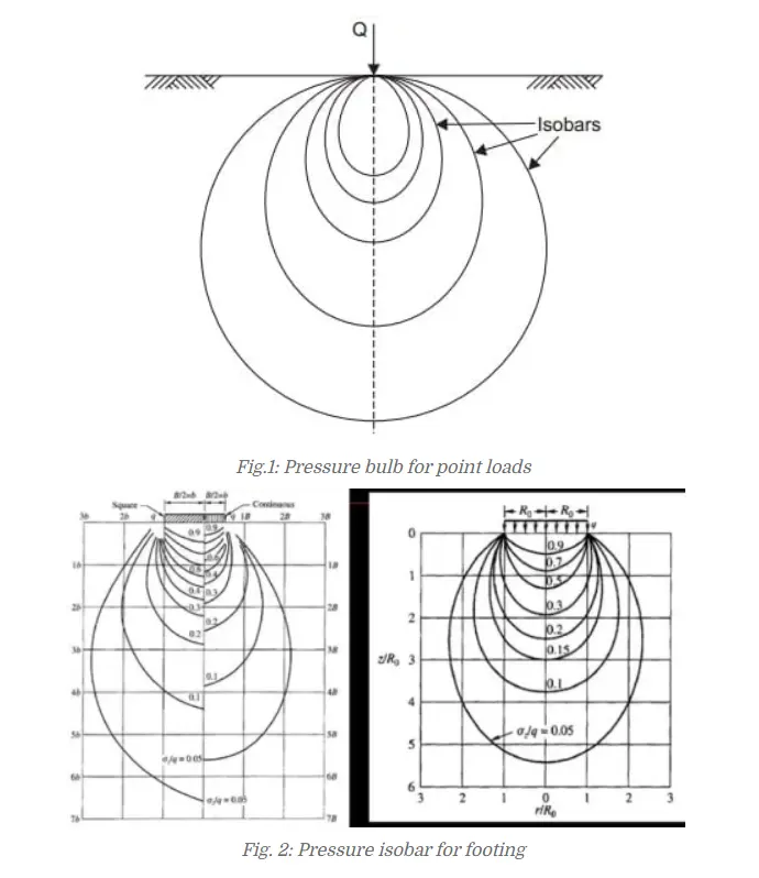
2) The "bulb of pressure" theory is a concept used to explain how piles in a group interact with the soil to distribute loads. It refers to the idea that the load applied to a pile group creates a zone of influence or "bulb" of increased stress in the soil around each pile. The interaction of these stress bulbs contributes to the load distribution among the piles.
Here's a brief overview of how the spacing of piles is determined and a description of the bulb of pressure theory:
Spacing of Piles in a 6-Pile Group:
-
Load Distribution: Determine the total load that the pile group needs to support from the structure above. This load is distributed among the piles based on their relative stiffness and load-bearing capacity.
-
Pile Capacity: Calculate the individual capacity of each pile to support its share of the load. This involves considering factors such as the pile's diameter, length, material properties, and the soil's bearing capacity.
-
Spacing Calculation: The spacing between piles is generally determined so that the stress distribution in the soil allows each pile to carry its share of the load without excessive settlement or overloading. A commonly used guideline is to maintain a distance between adjacent piles that is at least 3 times the diameter of the piles.
-
Group Efficiency: Piles in a group interact with each other which might lead to some degree of load-sharing. However, the efficiency of load-sharing decreases as the distance between piles increases. Therefore, the spacing is often chosen to achieve a balance between efficient load distribution and practical construction constraints.
Bulb of Pressure Theory:
The "bulb of pressure" theory explains the distribution of stresses in the soil due to the loading of piles. When a pile is loaded, it transfers the load to the soil, creating a zone of increased stress around the pile. In a pile group, these stress zones overlap and interact, contributing to the load distribution.
Here's a basic description of the stress distribution using the bulb of pressure theory:
-
Compressive Zone: The zone directly below the pile tip experiences increased vertical stress due to the load applied by the pile. This zone is known as the compressive zone.
-
Tension Zone: As the load is transferred to the soil, the soil particles experience lateral stresses. This creates a "tension bulb" surrounding the compressive zone. The soil here experiences reduced vertical stress.
-
Neutral Plane: Between the compressive and tension zones, there's a region known as the "neutral plane" where the stress change is minimal.
-
Bulb of Pressure: The combined effect of the compressive and tension zones results in a roughly bulb-shaped zone of increased stress around each pile. In a pile group, these stress bulbs interact, leading to a more distributed load-bearing behaviour.
3) To calculate the reaction exerted on the group of piles from the pier of the bridge.
Given Data -
- Total vertical reaction (P) = 5929 kN
- Total moment about L-L axis (ML) = 1092 kN.m
- A total moment about the T-T axis (MT) = 530 kN.m
- Total horizontal force along L-L axis (HL) = 83kN
- Total horizontal force along T-T axis (HT) = 172 kN
Assumption -
- Total no of piles (n) = 8 Nos.
- Dia of Pile = 1.2 M
- Distance between the p = 3.6 in both directions.
- Offset on both ends = 150 mm.
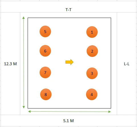
Plan of pile cap
Coordinate xi, yi are given as input by measuring the distance from the origin (0,0)
| Pile No. | Longitudinal | Transverse | n | xi2 | yi2 |
| xi | yi | ||||
| 1 | 1.8 | 5.4 | 1 | 3.24 | 29.16 |
| 2 | 1.8 | 1.8 | 1 | 3.24 | 3.24 |
| 3 | 1.8 | -1.8 | 1 | 3.24 | 3.24 |
| 4 | 1.8 | -5.4 | 1 | 3.24 | 29.16 |
| 5 | -1.8 | 5.4 | 1 | 3.24 | 29.16 |
| 6 | -1.8 | 1.8 | 1 | 3.24 | 3.24 |
| 7 | -1.8 | -1.8 | 1 | 3.24 | 3.24 |
| 8 | -1.8 | -5.4 | 1 | 3.24 | 29.16 |
| Sum (n) | ∑ (xi2) | ∑ (yi2) | |||
| 8 | 25.92 | 129.6 | |||
Load on each pile = p/n+ML×(xi/∑xi^2)+MT×(yi/∑yi^2)
Solution -
Load on pile 1
= 5929/8+1092×(1.80/25.92)+530×(5.40/129.6)
= 839.04 kN
Load on pile 2
= 5929/8+1092×(1.80/25.92)+530×(1.80/129.6)
= 824.31 kN
Load on pile 3
= 5929/8+1092×(1.80/25.92)+530×(−1.80/129.6)
= 809.59 kN
Load on pile 4
= 5929/8+1092×(1.80/25.92)+530×(−5.40/129.6)
= 794.875 kN
Load on pile 5
= 5929/8+1092×(−1.80/25.92)+530×(5.40/129.6)
= 687.375 kN
Load on pile 6
= 5929/8+1092×(−1.80/25.92)+530×(1.80/129.6)
= 672.65 kN
Load on pile 7
= 5929/8+1092×(−1.80/25.92)+530×(−1.80/129.6)
= 657.93 kN
Load on pile 8
= 5929/8+1092×(−1.80/25.92)+530×(−5.40/129.6)
= 648.20 kN