Week 10 - Challenge 1- Attachment Feature Creation (Ribs & Screw Boss)
Step 1: The entire Class A surface was analyzed properly for any surface discontinuities and other irregularities.
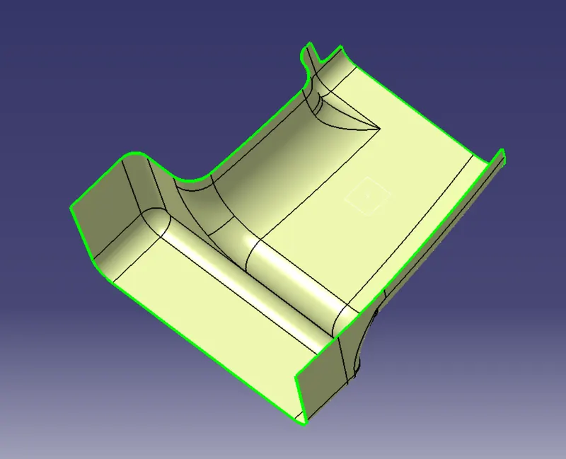
Step 2: Creation of Tooling Axis:
- A particular surface was identified as a potential surface on top of which the tooling axis was to be created.
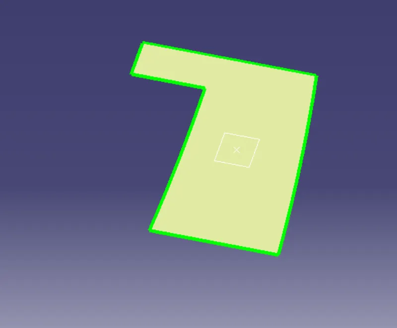
- A point was taken on this surface and a plane was created at this point with reference as xy plane.
- The intersection of the Class A surface and this plane was done which resulted in this profile:
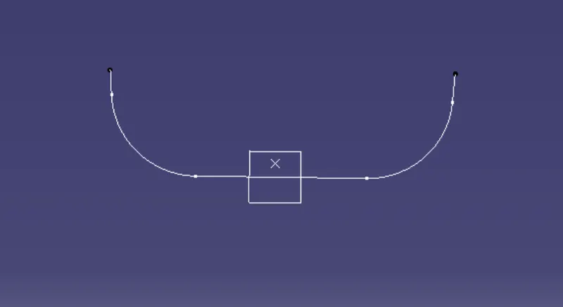
- Now two lines were made with line type as Point-Point with the help of the points obtained after the intersection.
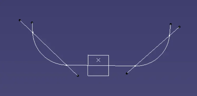
- Bisection of these lines was made.
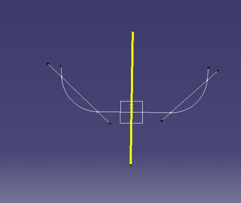
- Now daft analysis was done with reference to this line.
- This was clearing most of the surfaces. So this is the tooling axis.
Step 3: Creation of Class B surface.
- An offset of Class A was taken just above it with a value of 2.5 mm.
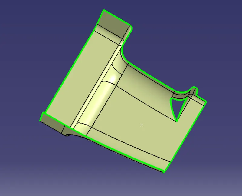
- The missing patch was fixed using the Multi-sections Surface command, and the entire surface was extrapolated 2 mm.
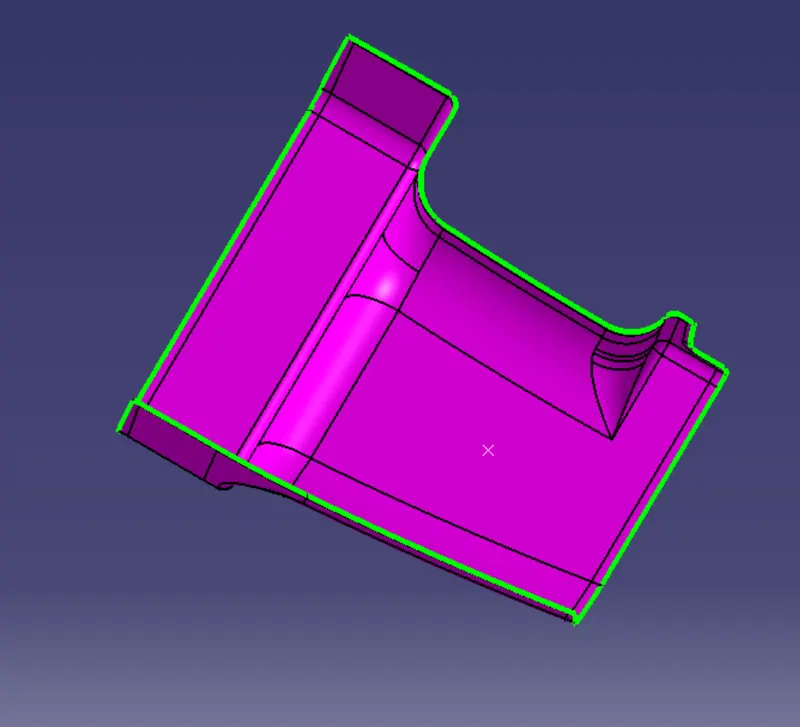
Step 4: Creation of Class C surface.
- The boundary of Class A was swept part by part with a draft of 3 degrees for the bottom boundaries and 90 degrees for the top boundaries.
- Then all of these individual swepts were joined together.
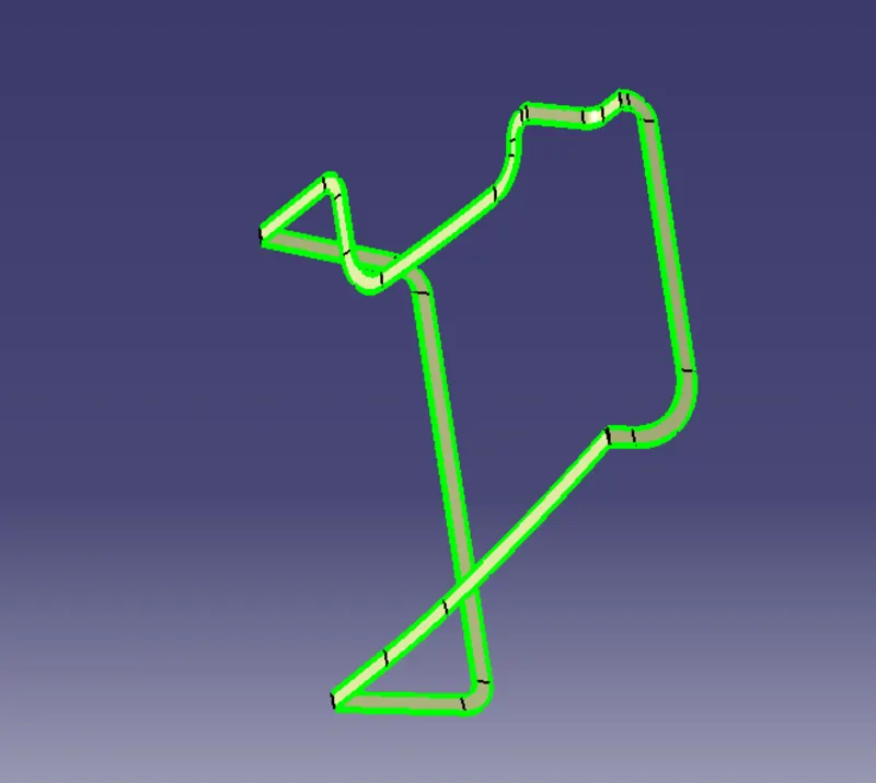
Step 5: Creation of Class A+C
- Class A and Class C surfaces were joined together.
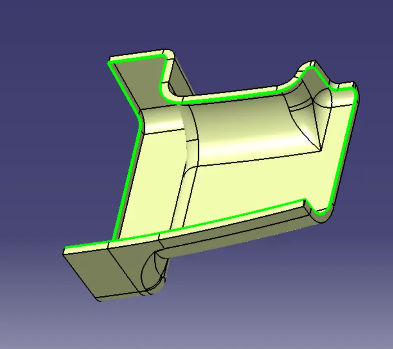
- Step 6: Class A+C and Class B were trimmed together.
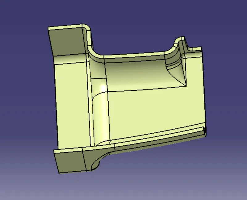
Step 7: Now this final trim was converted to a solid body using the Close Surface command.
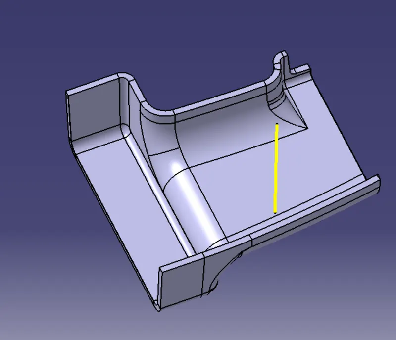
Step 8: Creation of Ribs.
- A line was made on the extracted surface i.e mentioned in Step 2. And it was extruded by 12.25 mm and then thickened it by 1 mm.
- A similar rib was made which is at a distance of 24 mm.
- These two ribs were added to the main solid body using Union Trim.
- Draft was given to them.
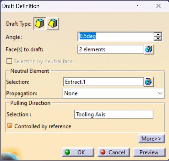
- Fillet of 2.5 mm was provided
Step 9: Screw Boss
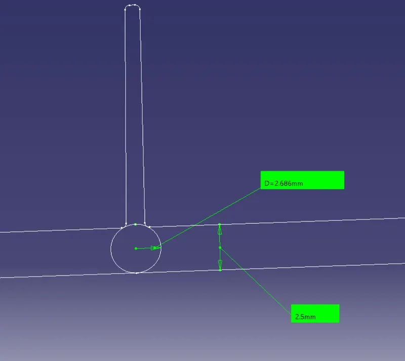
The following sketch was made on the same extracted surface.
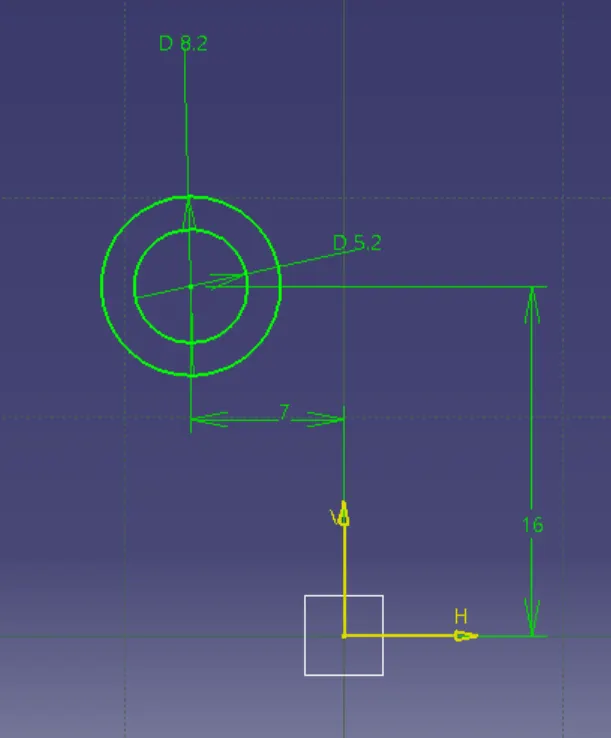
- This was extruded by 12 mm.
- Draft was provided to both outside and inside.
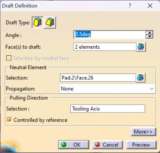
- A same screw boss was made on the same extracted face.
- Fillet of 2.5 mm was provided
- These two ribs were added to the main solid body using Union Trim.
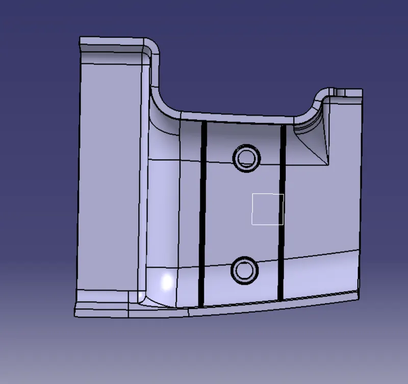
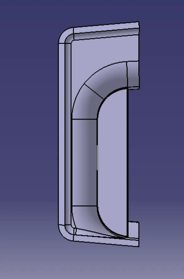
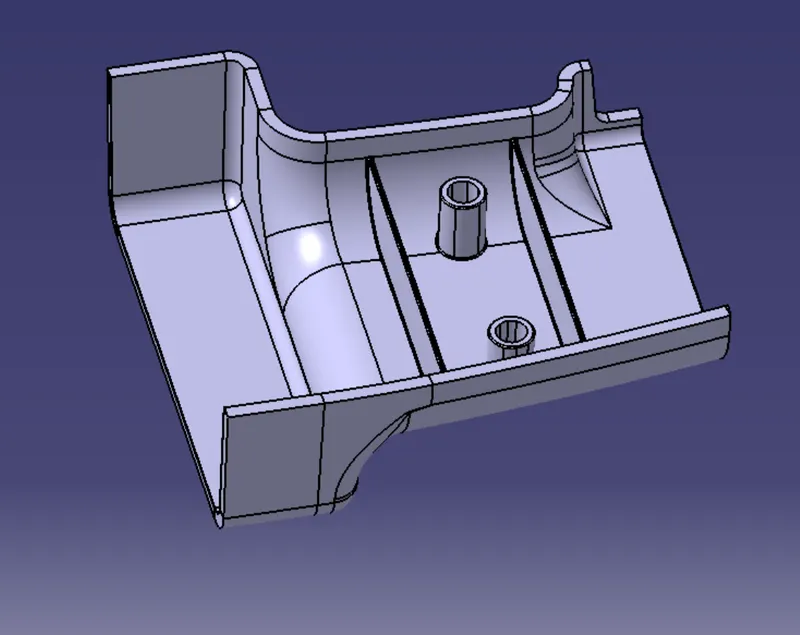
Draft analysis :
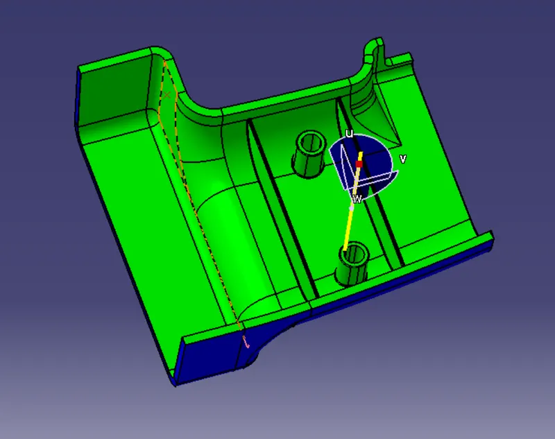
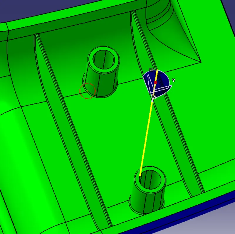
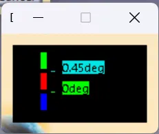
The ribs and screw bosses were clearing the given draft of 0.5 degrees.
Rib root thickness analysis:
Rib root thickness should not be more than 30% greater than the wall thickness.
The rib root thickness is within 1.3 x of the thickness of the main body. This is appropriate.
Conclusion:
The design part body and its engineering features were following all the design rules mentioned.