Week 10 - Challenge 1- Attachment Feature Creation (Ribs & Screw Boss)
Door Handle's Ribs and Screw Boss Report
Aim :
- To create Tooling axis and Conduct Draft analysis for both the Class A and Final Solid part.
Objective :
Ribs and Screw Boss Report:
- To create the Final Solid Part by using the given Class A.
- To create the Tooling Axis.
- To create the Ribs as per the design rule.
- To create the Screw Boss as per the design rule.
- To Draft analysis the obtained Final solid part, Class A, Ribs and Screw bars using the created Tooling Axis.
Introduction :
Tooling Axis:
- The Tooling Axis is to show in what direction does the core and cavity moves.
- It also created to give a draft angle for the final solid part.
Draft Analysis:
- The draft analysis is done on the basis of the Tooling Axis in order to find whether the final product is done as per the Design rules.
- The Draft angle which is assigned to the Tooling Axis defines the analysis.
- The Nominal Draft angle for the plastic product is 3 degree.
Class A:
- Class A is the aesthetic surface.
- Class A is created on the basis of a concept sketch or by the predefined shape on basis of the design engineer and customer requirement.
- Class A is given to the Product design engineer in order to get the final solid part.
Class B:
- Class B is the surface that is created by the product design engineer in order to get the final product from the class A surface.
- Class B is created based on the thickness that the final solid part should be.
- In other words, Class B is an Extended version of Class A with some thickness gap between them.
Class C:
- Class C is the surface that is designed by the product design Engineer.
- Class C is created inbewteen Class A and Class B in order to connect them.
Ribs:
- Ribs are thin, wall-like features typically designed into the geometry of a part to add internal support to walls or other features like bosses.
Screw Boss:
- The Screw Boss is cylindrical-like feature where its support the geometry for postioning the screw.
Procedure :
Class A:
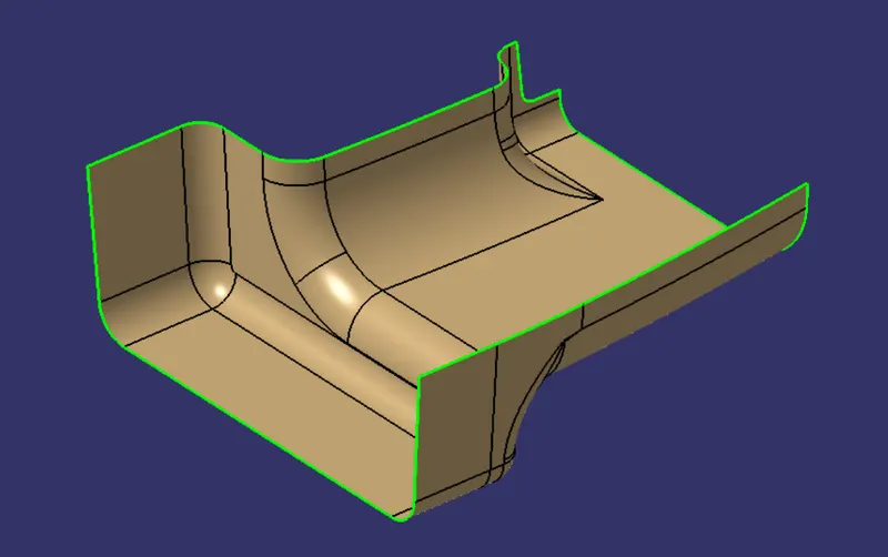
- The class A is taken from given Step file.
- Created class A is checked with the boundary tool.
Tooling Axis:
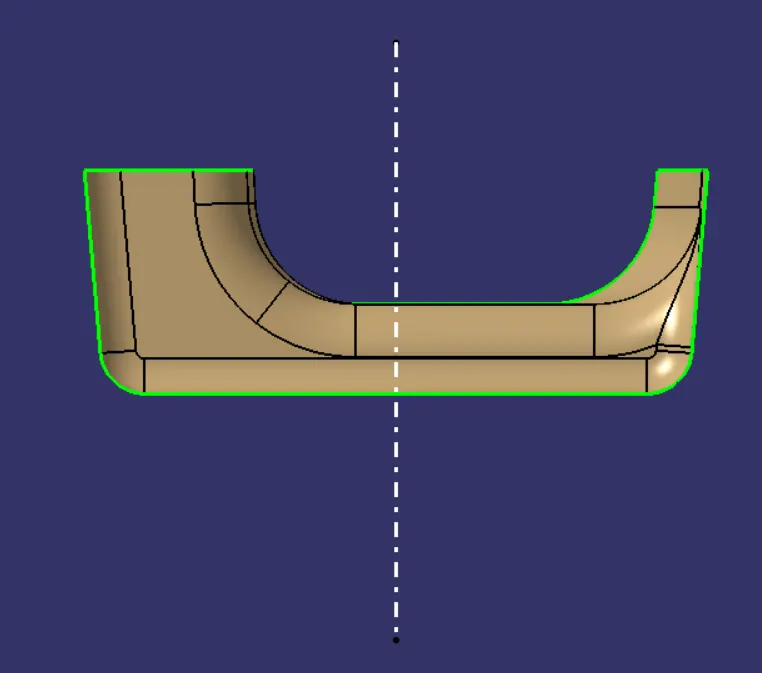
- The tooling for this can't created by using bisecting method.
- The tooling is created here by Axis method.
- In this the axis is selected where all the feature in the class A is clearly visible.
Draft Analysis on Class A:
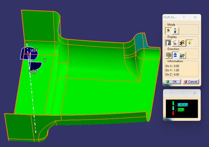
- The draft analysis is done on class A with the help of tooling axis.
- As you see in the below the given Class A is not correct.
Class B:
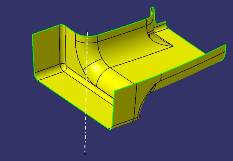
- The Class A is offseted to given 2.5mm.
- Then fillet which are not forming is created.
- Thus Class B is created.
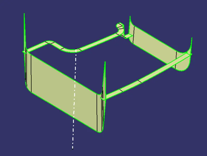
Class C:
- The class C formed by creating boundary and extract edge from class A.
- Class C are created in sperate patches.
- They are extrapolated and then trimed.
- Then in some areas joined together.
- Thus Class C is formed.
Final Operation:
- The Class A and Class C are joined together.
- Then joined Class a and Class C are trimed together to form a Closedsurface.
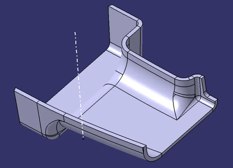
Solid Body:
- The Closed plastic surafce is converted to solid by using 'closesurface'.
- Switch from 'Generative surface design' to 'part design' to do it.
Draft Analysis of Solid:
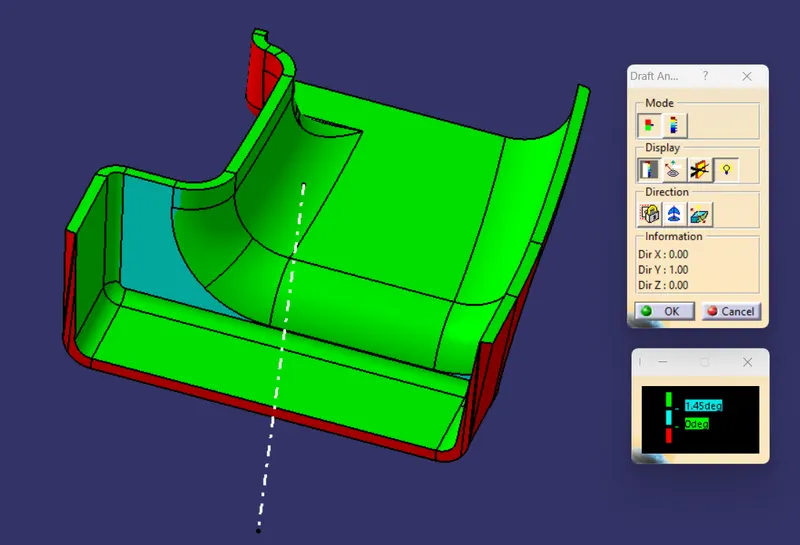
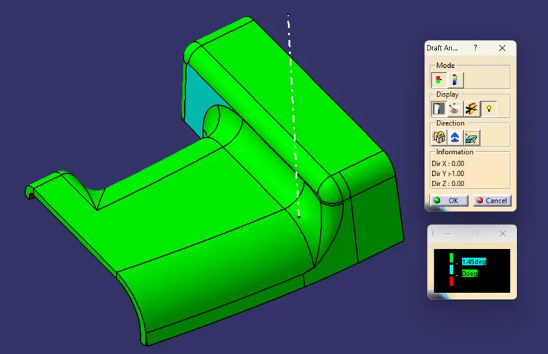
- The draft analysis on solid body is done.
- The draft analysis show the created solid is not correct due to error in given class A.
Ribs :
- Ribs are B-side feature which support the main body.
- As per given reference ribs are created.
- The extracted plane and point used for tooling creation are used to create the sketch for ribs.
- The sketch drawn is iso-constrained.
- Then the ribs are extrude to the height which are calculated.
- The extrude is converted to solid by using Pad.
- In pad 'thick' option is used.
- The ribs are then drafted to 0.5 degree.
- The fillets are applied to of radii 0.25 mm.
- The Ribs are then union trimmed with the Created solid body.
- In the uniontrim 'keep body' is selected.
- The 'Edge fillet' is given to the ribs on the joining edges.
- Same procedure is followed to create the second rib.
Screw Boss :
- The Screw boss is also a B-side feature which support the main body.
- The extraction is created and the 'on surface ' in point tool used to create point.
- The Screw boss is designed for M6 thread.
- The Sketch are drawn based on the M6 thread requirement.
- The sketch drawn is iso-constrained.
- The drawn sketch is pad to height as per the design rule.
- The pad Screw boss is draft to 0.5 degree.
- The Screw Boss is drafted on both side.
- Then Support ribs created for the Screw Boss.
- The suport rib is created as per the design rule.
- Then created rib is draft to 0.5 degree and filleted to 0.25mm.
- The support rib is then union trimmed with screw boss.
- In union trim the remove body option is selected and inner part inside screw boss is selected.
- The Union trimmed Screw boss is again union trimed with main body.
- In it keep Body is selected and required body is selected.
- Same procedure is follwed for the second Screw Boss also.
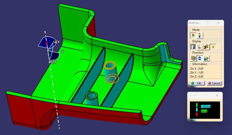
Final Draft Analysis :
- The draft analysis for final solid body with ribs and screw boss is done.
- As mentioned above the Class A is Not Correct so resulting Draft is not correct.
Conslusion :
- The given Class A is not correct so draft analysis which derived is wrong.
- All other Class B, Class C, Ribs and Screw Boss are created as per design rules.