Photo Realistic Rendering
American Chopper Design Project using Solidworks
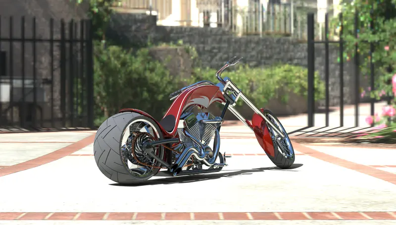
Design, Assembly and Rendering of an American Chopper Motorcycle using Solidworks
Aim and Objective:
- To sketch and design every exterior part of the American chopper under a part modelling environment with suitable sketches and commands using Solidworks.
- To assemble the modelled parts of the American chopper to form a complete chopper model in the assembly environment.
- To create a photorealistic rendering of the American chopper using Photoview360 and Solidworks Visualise.
Introduction:
A chopper is a type of custom motorcycle which emerged in California in the late 1950s. The chopper is perhaps the most extreme of all custom styles, often using radically modified steering angles and lengthened forks for a stretched-out appearance. They can be built from an original motorcycle which is modified ("chopped") or built from scratch. Some of the characteristic features of choppers are long front ends with extended forks often coupled with an increased rake angle, hardtail frames (frames without rear suspension), very tall "ape hanger" or very short "drag" handlebars, lengthened or stretched frames, and larger than stock front wheels.
About the Solidworks Design Tool :
SolidWorks is a solid modelling computer-aided design (CAD) and computer-aided engineering (CAE) program published by Dassault Systems. According to the publisher, over two million engineers and designers at more than 165,000 companies were using SolidWorks as of 2013. Solidworks has three basic environments namely: Part, Assembly and Drawing.
1.Part modelling or 3D solid modelling in Solidworks uses 2 approaches parametric modelling approach and feature based approach simultaneously, wherein parameters determine the shape and geometry of the solid model or the assembly.
2.Assembly of various parts can be done in the assembly environment. In this environment the Mates determine the final assembly and relation of various parts to each other. Mates are categorized into General, Advanced and mechanical mates.
3.Drawing environment is mainly used to create 2D sheets with all main views of the solid parts and assembly. These sheets also include details used for manufacturing of the component such as geometric dimensions, tolerances and section views of the required part/assembly.
Part Modelling :
Modelling in general means creating a virtual prototype of an item. It can be used for various purposes. Consider the engine of a car. It has hundreds of parts. Each part can be modelled separately and then can be assembled together to get the engine's final form. This type of modelling is called part modelling.
Assembly :
Assembly is a technology and method used by Computer-Aided design and product visualization computer software systems to handle files that represent components with in the product. The components within the assembly are represented as solid or surface models. The individual data files describing the 3D geometry of individual components are assembled together through a number of sub-assembly levels to create an assembly describing the whole product.
It is also can be defined as an collection of independent model parts which are brought together in an assembly environment to define a larger, more complex product representation.
Design Methodology or Modelling and Assembly Approach :
1. Bottom-Up Assembly Approach
- The individual parts are created independently, inserted into the assembly, and located and oriented (using the mating conditions) as required by the design.
- The bottom-up approach is preferred technique if the parts have already been created (off the shelf).
- It allows the designer to focus on the individual parts. It also makes it easier to maintain the relationship and regeneration behavior of parts than in the top-down approach.
2. Top-Down Assembly Approach
- In this approach, the assembly file is created first with an assembly layout sketch.
- The parts are made in the assembly file or the concept drawing of the parts are inserted and finalized in the assembly file.
- In other words, the final geometry of the parts have not been defined before bringing them into the assembly file. The approach is ideal for large assemblies.
3. The Middle Out Approach
- The middle out assembly modeling approach is the mixture of the bottom-up and top-down approaches.
- This type of assembly model is usually constructed with most of the parts already created and additional parts are designed and created using the assembly for construction information.
PARTS TO BE MODELLED IN CHOPPER:
The following parts of the chopper are modeled in Solidworks and assembled together.
- Transmission Belt
- Kickstand
- Front Fender
- Rear Fender
- Oil Tank
- Chain
- Pedal
- Front Wheel
- Rear Wheel
- Front Fork
- Chassis
- Engine
- Gas Tank
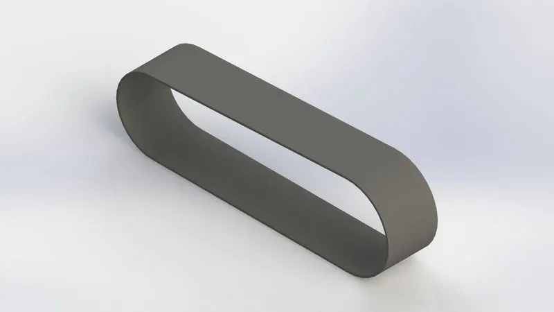
1. TRANSMISSION BELT :
The transmission belt is a loop of flexible material used to link two or more rotating shafts mechanically, it is used as a source of motion, to transmit power efficiently. It is used to transmit the power from the Engine to the Gearbox.
Commands Used: Sketch, Offset Entities, Extrude, Fillet, Appearances.
Sketch – It is the 2D representation with respect to the plane /view. In Solidworks different sketch options are available such as line, arc, circle, rectangle, spline.
Offset Entities - It is used to create one or more sketch entities, selected model edges, or model faces by a specified distance.
Extrude – It used to covert 2D sketch into a 3D model.
Fillet - Fillet/Round creates a rounded internal or external face on the part. You can fillet all edges of a face, selected sets of faces, selected edges, or edge loops.
Appearances – It is used to apply color and optical properties to the entire part, or selected faces, features (including surfaces or curves), or bodies. You can also modify the color by manipulating the shaded appearance of the model.
2. KICKSTAND :
The kickstand is a swiveling metal bar for holding a bicycle, motorcycle, or another two-wheeled vehicle upright when it is not being ridden and is used for the safety of the vehicle. It is pivoted to the axle in such a way that it can be kicked down below the frame.
Commands Used: Sketch, Loft, Dome, Extrude Boss, Extrude cut, Fillet, Split, Appearances.
Loft - The loft feature in SOLIDWORKS allows you to generate complex geometry in a single feature. It does this by interpolating surfaces between various cross-sections of a model. These cross-sections can be sketches, faces, or edges. In the loft interface, these cross-sections are considered “Loft Profiles”.
Dome - Dome, in architecture, hemispherical structure evolved from the arch, usually forming a ceiling or roof over the surface/face being selected.
Extrude cut- The extrude cut feature is use to remove the unwanted material as per the modeled sketch, based on the design of the sketch the material is removed. You can cut in both directions and mainly used for creating holes, channels, slots, etc.
Split - Split Line tool is used to project an entity (sketch, solid, surface, face, plane, or surface spline) onto other surfaces or curved/planar faces. You are also able to split faces on multiple bodies with one command.
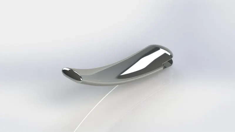
3. FRONT FENDER :
Fenders make a tremendous difference when you are riding roads that are wet from the drizzle, recent rain, or snowmelt. In a hard rain, you may become wet with clean rain from above, but fenders will protect your body and bicycle from the mud and sand kicked up from dirty puddles and rivulets.
Commands Used: Sketch, Offset entities, Trim entities, Revolve, Dynamic mirror, Split, Appearances.
Trim entities - Trim is used to remove unwanted sketch entities or extra portions of the sketch. It works based on some reference points, edges.
Revolve - Revolve is the process of creating a revolved profile with reference of the sketch and the axis of rotation. The profile can be created with the revolution upto 360 axis rotation.
Dynamic mirror - A really quick tip for instantly creating symmetry within a sketch in SOLIDWORKS. As you create a sketch on one side of the centreline, the Dynamic Mirror tool will automatically create a symmetrical shape on the other side, which has the same relations as the sketch you're creating.
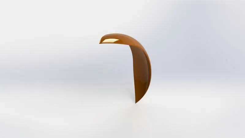
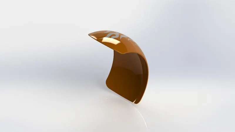
4. REAR FENDER :
The use of the rear fender is the same as the front fender. The rear fender is mounted on the chassis of the rear part above the Rear Wheel.
Commands Used: Sketch, Offset entities, Trim entities, Revolve, Shell, Appearances.
Shell: Shell is used to create a thickened surface either it can be done in the interior or exterior surface. The shell tool hollows out a part, leaves open the faces you select, and creates thin-walled features on the remaining faces. If you do not select any face on the model, you can shell a solid part, creating a closed, hollow model. You can also shell a model using multiple thicknesses.
5. OIL TANK :
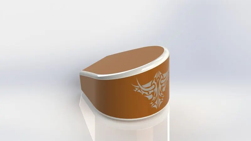
Oil tanks are used to store engine oil which from there is pumped to the engine and other parts of an automobile for lubrication and maintenance.
Commands Used: Sketch, Extrude, Combine, Fillet, Shell, Appearances.
Combine - It used to combine two or more bodies.
6. CHAIN :
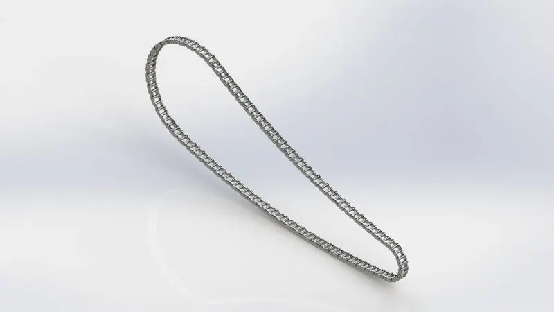
Chains are mainly used in chain and sprocket drives these are used to perform three basic functions: transmitting power, conveying materials, and timing purposes. Chain and sprocket drives are used to transmit power from one component to another. Specifically, they transfer speed and torque through the use of a linked chain and sprockets. In automobiles, roller chains are used in these drives to transmit power and torque.
Commands Used: Sketch, Trim, Fillet, Blocks, Extrude, Patterns
Blocks - You can make, save, edit, and insert blocks for drawing items and sketch entities that you use often, such as standard notes, title blocks, label positions, and so on. You can attach blocks to geometry or to drawing views, and you can insert them into sheet formats.
Patterns – Pattern repeats the selected feature in an array based on a seed feature. You can create a linear, circular, curve driven, a fill pattern or use sketch points or table coordinates to create the pattern.
7. PEDAL :
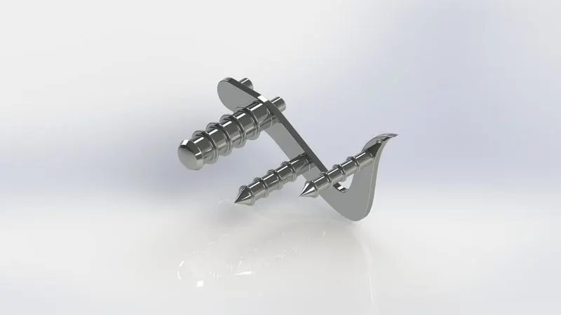
The pedal is used to rest feet while driving a two-wheeler. It is an extended piece from the chassis which is used for resting feet to maintain balance and comfort while riding the vehicle.
Commands Used: Sketch, Extrude, Fillet, Linear pattern, Dome, Chamfer, Appearances.
Linear pattern- Linear pattern create multiple instances of one or more features that you can space uniformly along one or two linear paths. The pattern is created based on the reference edge, face, etc.
Chamfer - A chamfer or is a transitional edge between two faces of an object. Sometimes defined as a form of bevel, it is often created at a 45° angle between two adjoining right-angled faces.
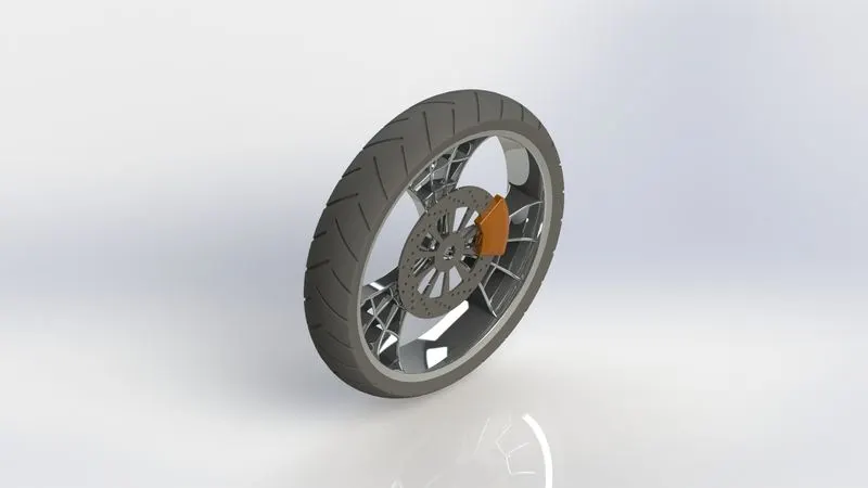
8. FRONT WHEEL :
A wheel is a circular block of a hard and durable material whose center has been bored a circular hole through which is placed an axle bearing about which the wheel rotates when a moment is applied by gravity or torque to the wheel about its axis.
Wheel consists of Rim and Brake Caliper.
Rim: The rim is the "outer edge of a wheel, holding the tire". It makes up the outer circular design of the wheel on which the inside edge of the tire is mounted on vehicles such as automobiles.
Brake Caliper: A disc brake is a type of brake that uses the calipers to squeeze pairs of pads against a disc or "rotor" to create friction. This action slows the rotation of a shaft, such as a vehicle axle, either to reduce its rotational speed or to hold it stationary. The energy of motion is converted into waste heat which must be dispersed.
Motorcycle wheels are made to cope with radial and axial forces. They also provide a way of mounting other critical components such as the brakes, final drive, and suspension. Wheels, and anything directly connected to them, are considered to be unsprung mass.
Commands Used: Sketch, Revolve, Trim, Fillet, Extrude, Revolve Cut, Linear Pattern, Chamfer, Cut Extrude, Circular Pattern, Appearances.
Revolve Cut - The Revolve cut command is used to cut a solid geometry by revolving about an axis. The axis may be a reference axis.
Circular Pattern - It is used to create multiple instances of one or more features that you can space uniformly around an axis.
9. REAR WHEEL :
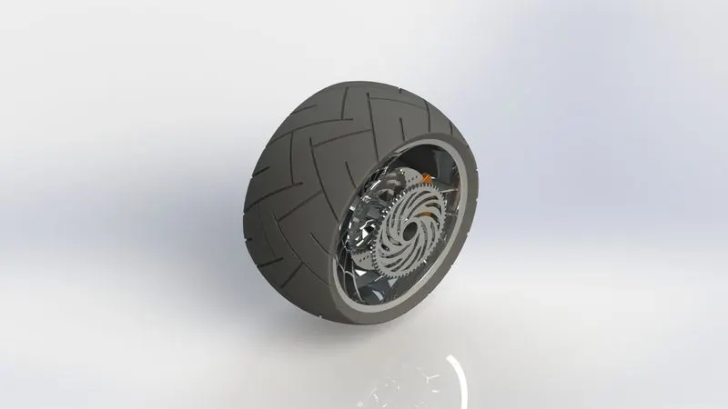
Rear wheel is situated at rear portion of chassis. The rear wheel carries the large sprocket and disc. The power is transmitted to rear wheel from the gearbox through the chain.
Commands Used: Sketch, Revolve, Trim, Fillet, Extrude, Planes, Revolve cut, Linear pattern, Chamfer, Fillet, Extrude cut, Circular Pattern, Appearances.
10. FRONT FORK :
Motorcycle wheels are made to cope with radial and axial forces. They also provide a way of mounting other critical components such as the brakes, final drive, and suspension. Wheels, and anything directly connected to them, are considered to be unsprung mass.
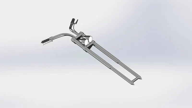
The front fork prevents excessive weight on the front wheel during drastic sudden applications the break, softens bumping when driving on rough road surfaces. The front fork maintains proper damping through traction with the road surface.
Front fork connects a motorcycle's front wheel and axle to its frame, typically via a yoke, also known as a triple clamp, which consists of an upper yoke joined to a lower yoke via a steering stem, a shaft that runs through the steering head, creating the steering axis. Most forks incorporate the front suspension and front brake and allow the front wheel to rotate about the steering axis so that the bike may be steered.
Commands Used: Sketch, Extrude, Trim, Revolve, Split, Plane, Convert entities, Move/Copy, Dome, Mirror, Combine, Reference Geometry, Project Curve, Sweep, Appearance.
Move/copy Body- Using this command you can move, rotate and copy solid ad surface bodies or place them using mates
Mirror- Mirroring is another way that Solid works can create a copy of an existing object. Additionally, you must choose a plane to mirror parts. In most cases, you need to create your own plane to have the mirror done the way you need.
Project Curve- A projected curve is typically used either in sweep and loft as path or guide curve. They are made by using two sketches to a single curve or use a sketch to project on a surface.
Sweep- The Sweep command is used to create solid features by sweeping a closed profile along an open or closed path.
Reference Geometry- Reference geometry is used to create a reference plane, axis, co-ordinate system based on one, two or three references.
11. CHASSIS :
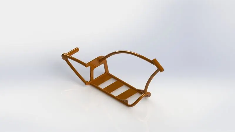
Chassis is the main support structure of the vehicle which is also known as ‘Frame’. A chassis is the load bearing framework of a chopper which structurally supports its function and construction. All the parts of a vehicle wheels, transmission, fuel tank etc. are mounted on it. It bears all the stresses on the vehicle in both static and dynamic conditions. In a vehicle, it is analogous to the skeleton in living organisms. The origin of the word Chassis lies in the French language. Every vehicle whether it is a two-wheeler or a car or a truck has a chassis-frame. However, its form obviously varies with the vehicle type.
- Supports or bears the load of the vehicle body.
- Provide the space and mounting location for various aggregates of vehicles.
- Supports the weight of various systems of the vehicle such as the engine, transmission, etc.
- Supports a load of passengers as well as the luggage.
- Withstands the stresses arising due to bad road conditions.
- Withstands stresses during braking and acceleration of the vehicle.
Commands Used: Sketch, Offset, Convert entities, Project curve, Trim, Plane, Sweep, Split, Revolve, Cut extrude, Fillet, Combine, Appearance.
Convert Entities - You can create one or more curves in a sketch by projecting an edge, loop, face, curve, or external sketch contour, set of edges, or set of sketch curves onto the sketch plane.
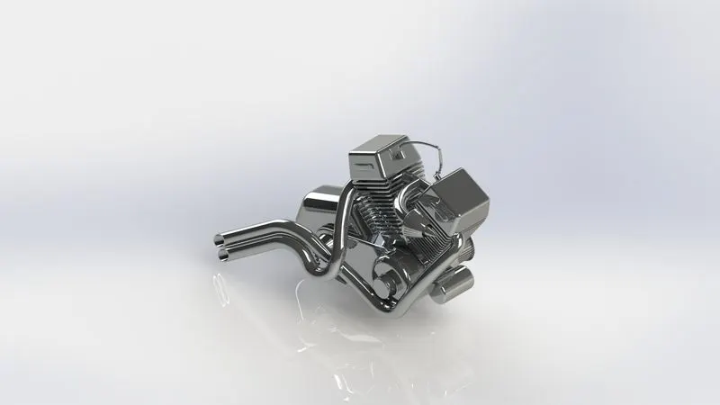
12. ENGINE :
An engine is a machine designed to convert the chemical energy of a fuel into thermal or heat energy and then the thermal energy into mechanical energy or mechanical work Engine consists of pistons, a cylinder block and a head, which contains the valve train. The pistons move up and down in the cylinder block, driven by explosions of a fuel-air mixture that has been ignited by a spark. Valves open and close to allow the fuel-air mixture to enter the combustion chamber. As the pistons move up and down, they turn a crankshaft, which transforms the energy from the pistons into rotary motion. The rotational force of the crankshaft is transmitted, via the transmission, to the rear wheel of the motorcycle.
Motorcycle engines are generally classified by one of three characteristics the number of cylinders they possess, the capacity of their combustion chambers or the number of strokes in their power cycles.
Motorcycle engines work the same way that car engines do. They consist of pistons, a cylinder block, and a head, which contains the valve train. The pistons move up and down in the cylinder block, driven by explosions of a fuel-air mixture that has been ignited by a spark. Valves open and close to allow the fuel-air mixture to enter the combustion chamber. As the pistons move up and down, they turn a crankshaft, which transforms the energy from the pistons into rotary motion. The rotational force of the crankshaft is transmitted, via the transmission, to the rear wheel of the motorcycle.
Motorcycle engines are generally classified by one of three characteristics: the number of cylinders they possess, the capacity of their combustion chambers or the number of strokes in their power cycles.
Commands Used: Sketch, Convert entities, Trim, Revolve, Extrude, Extrude cut, Offset, Dome, Fillet, Project curve, Composite curve, Sweep, Mirror, Circular pattern, Split.
Composite curve - The composite curve tool provides the ability to create composite curves by combining two curves. The composite curve is the combination of the two projected curves.
13. GAS TANK :
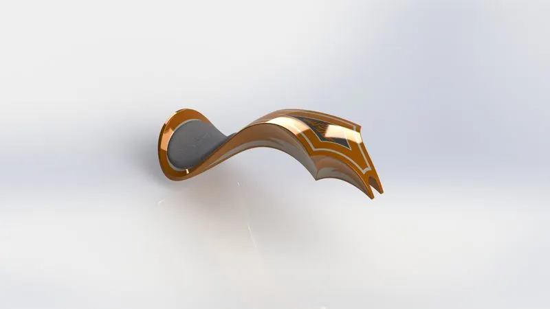
The gas tank acts as a reservoir to meet the fuel requirements of the chopper.
- Storage of fuel: the system must contain a given quantity of fuel and must avoid leakage and limit evaporative emissions.
- Filling: the fuel tank must be filled in a secure way, without sparks.
- Provide a method for determining the level of fuel in the tank, gauging (the remaining quantity of fuel in the tank must be measured or evaluated).
- Venting (if over-pressure is not allowed, the fuel vapors must be managed through valves).
- Feeding of the engine (through a pump).
- Anticipate potentials for damage and provide safe survival potential.
Commands Used: Sketch, Trim, Project curve, Convert entities, Sweep cut, Sweep surface, Loft surface, Fill surface, Surface trim, Knit surface, Sweep cut, Fillet.
Sweep Surface - Creates a surface feature by sweeping an open or closed profile along an open or closed path.
Loft Surface - Loft Surfaces are surfaces generated by multiple 3D Curves or existing edges creating a smooth tangency between the selected curves.
Sweep Cut - It is used to cut a solid geometry by sweeping a closed profile along a closed or open path.
Fill Surface - The Filled Surface feature constructs a surface patch with any number of sides, within a boundary defined by existing model edges, sketches, or curves, including composite curves.
Surface Trim - Primarily used to cut away material from a surface, and provides two modes: Standard and Mutual. In Standard mode, a single selection is defined as a Trim Tool, and target surfaces are trimmed accordingly. In Mutual mode, multiple surfaces are trimmed with respect to each other.
Surface Knit - It is used to combine two or more faces and surfaces into one.
ASSEMBLY OF AMERICAN CHOPPER :
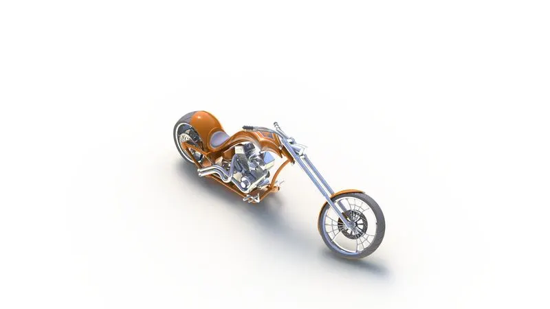
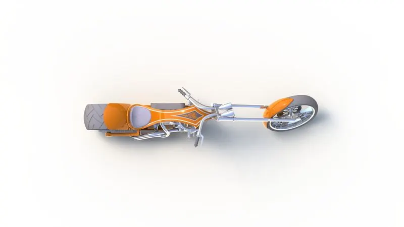
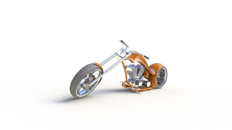
The chopper assembly is done in the assembly environment all the parts which are modelled are imported to the assembly environment one the component is fixed and the remaining part is assembled with suitable mates to get the final assembly of the chopper.
Assembly is done in the assembly environment by inserting all the modeled parts of the chopper using insert part option.
Parts of the chopper are fixed in the assembly environment by giving possible mate conditions or by fixing the planes.
You can build complex assemblies consisting of many components, which can be parts or other assemblies, called subassemblies. For most operations, the behavior of components is the same for both types.
Adding a component to an assembly creates a link between the assembly and the component. When SOLIDWORKS opens the assembly, it finds the component file to show it in the assembly. Changes in the component are automatically reflected in the assembly.
MATES :
Mates create geometric relationships between assembly components. As you add mates, you define the allowable directions of linear or rotational motion of the components. You can move a component within its degrees of freedom, visualizing the assembly's behavior.
Mates are used to create the relation between two mating parts it may be parallel, concentric, perpendicular, angular, etc., With respect to the fixed part, all the other parts can be mated.
After defining the mates, the relative motions i.e., angular, linear movement between the mating parts are defined in the environment.
TYPES OF MATES
The various types of mates available in Solidworks are:-
- Standard Mates - Angles, Coincident, Concentric, Distance, Lock Parallel, Perpendicular, Tangent mates.
- Advanced Mates - Limit, Linear/Linear coupler, Path, Symmetry, Width mates.
- Mechanical Mates - Cam-follower, Gear, Hinge, Rack and Pinion, Screw, and Universal joint mates.
RENDERS OF AMERICAN CHOPPER ASSEMBLY :
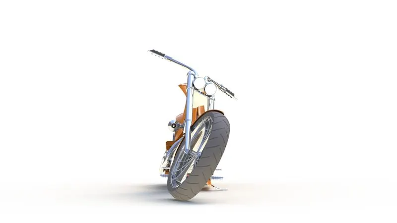
Front View
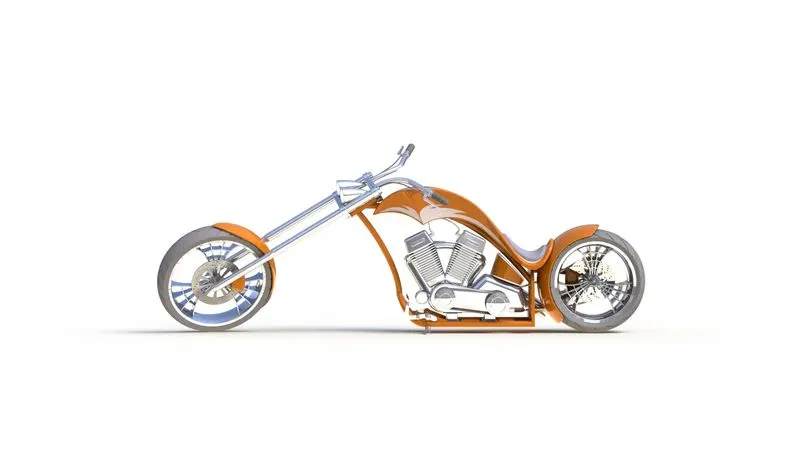
Side View
Isometric View
Top View
Camera Setup View
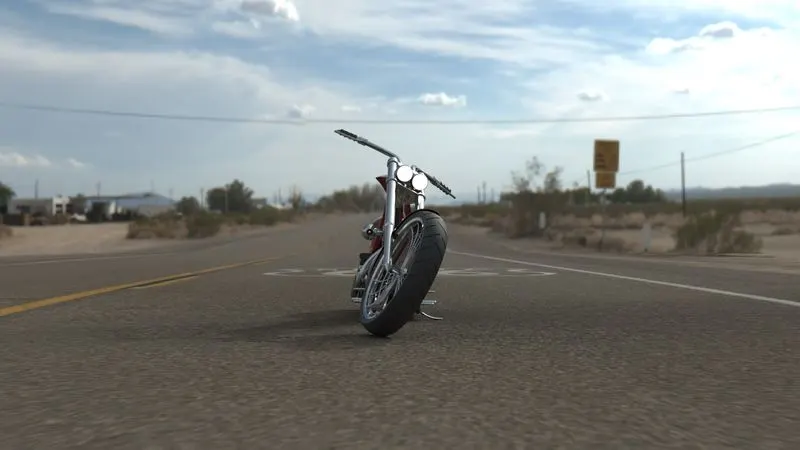
PHOTOREALISTIC RENDERING OF AMERICAN CHOPPER :
Rendering is the automatic process of generating a photorealistic or non-photorealistic image from a 2D or 3D (or models in what collectively could be called a scene file) by means of the computer programs. Also, the results of displaying such a model can be called a render. A scene file contains objects in a strictly defined language or data structure; it would contain geometry, viewpoint, textures, lighting, and shading information as a description of the virtual scene. The data contained in the scene file is then passed to a rendering program to be processed and output to a digital image or raster graphics image file. The term "rendering" maybe by analogy with an "artist's rendering" of a scene.
Rendering is also defined as the process of creating realistic images of the Photorealistic model with the environment. Rendering has been done in two ways in solidworks. The following are the two ways:-
1. Photoview 360
2. Solidworks Visualize
In the photorealistic model, some of the mate conditions and positions are changed to render realistic models. Then the photorealistic model is rendered into realistic images with different views.
Front View
Back View
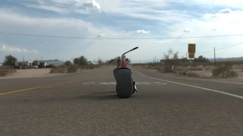
Left Side View
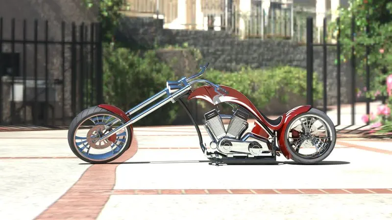
Right Side View
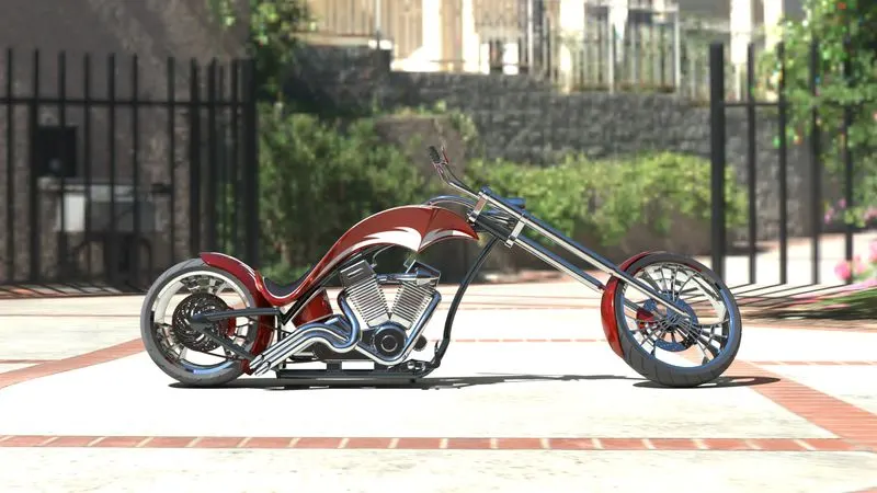
Top View
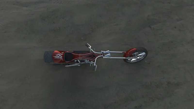
Camera Setup View
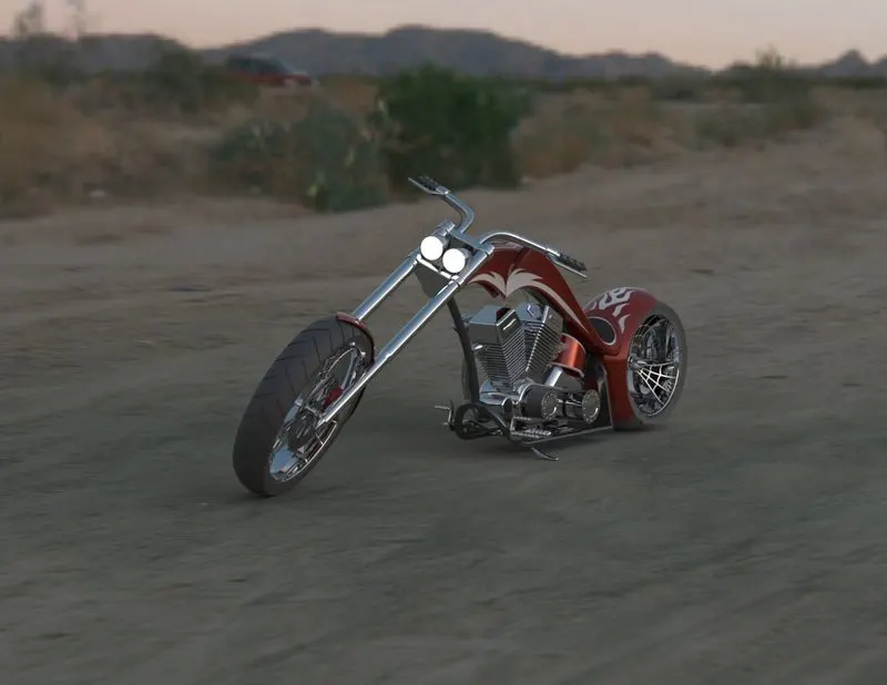
Isometric View
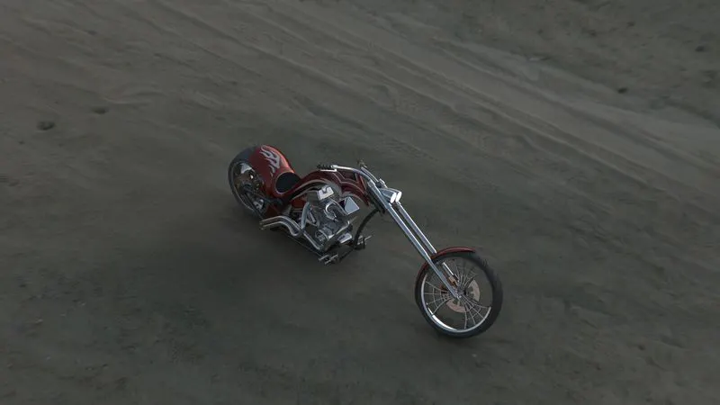
Conclusion :
- All the parts of the American chopper are modelled successfully under SolidWorks modelling environment.
- All the parts are inserted into the assembly environment and the American chopper is successfully assembled using Solidworks.
- The photorealistic image is successfully rendered with the use of the Photoview 360 & Solidworks visualize.