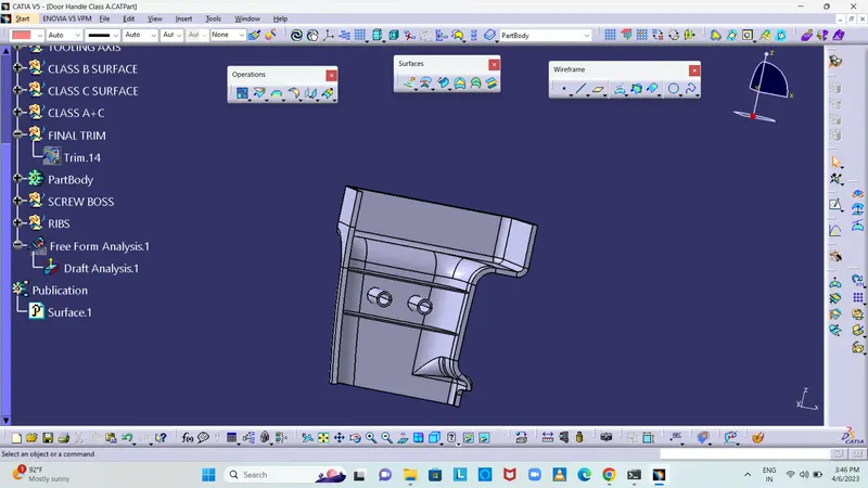
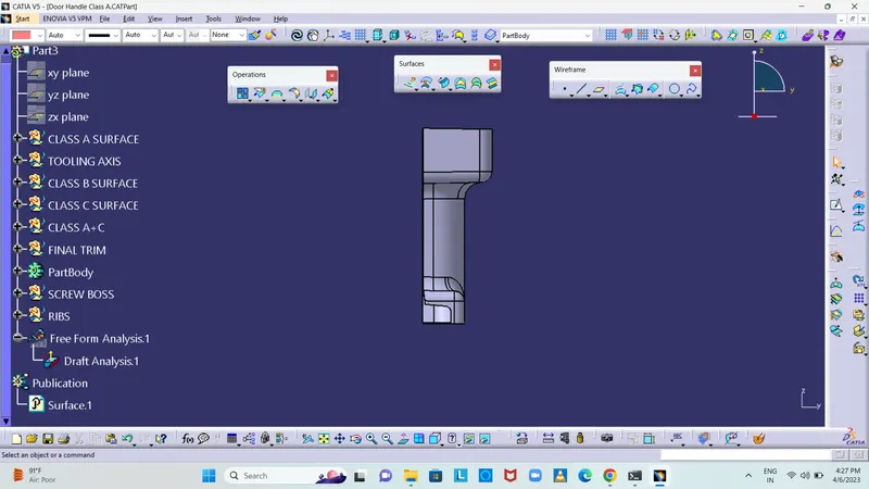
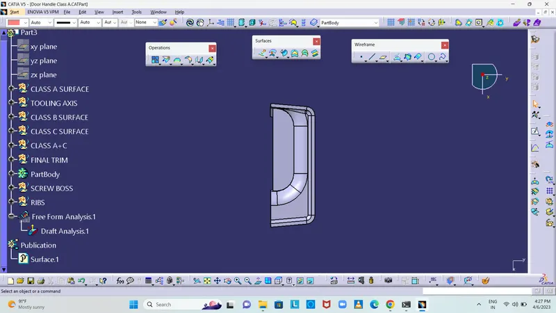
Week 10 - Challenge 1- Attachment Feature Creation (Ribs & Screw Boss)
Features used for design A-Class, B-Class, and C-Class.
- Line
Point
Axis system
Extrude
untrim
extrapolate
Extract
boundary
Join
Swept
fillet
close surface
Intersecting
Publication
General Guidelines for Bosses:
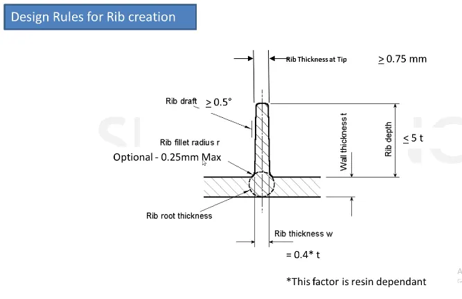
DESIGN RULE FOR RIB
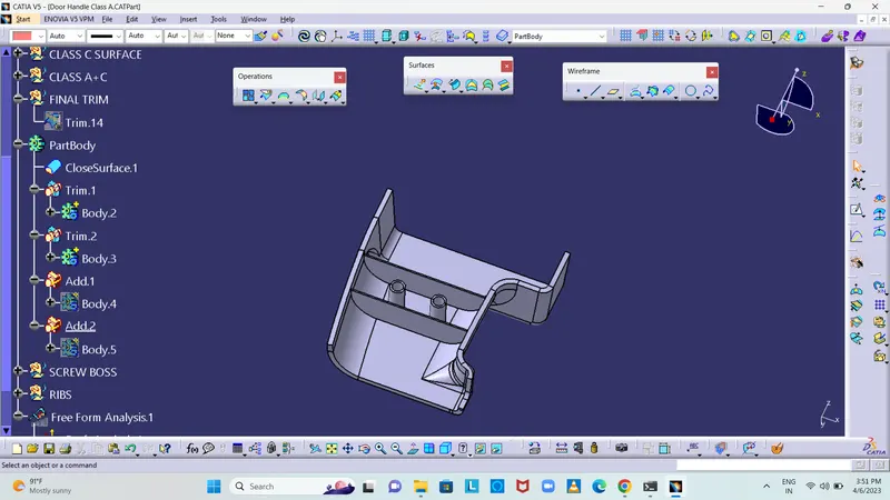
DESIGN RULE FOR SCREW BOSS
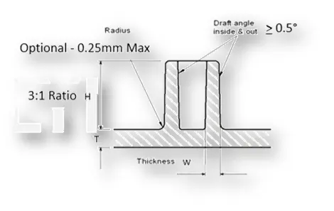
- Draft - 0.5 degrees on the walls of boss
- Thickness - Typically 40%* of the nominal wall at the base.
- Height to Diameter Ratio - 3:1
- Radii - 0.25mm maximum radii.
Tooling Axis:
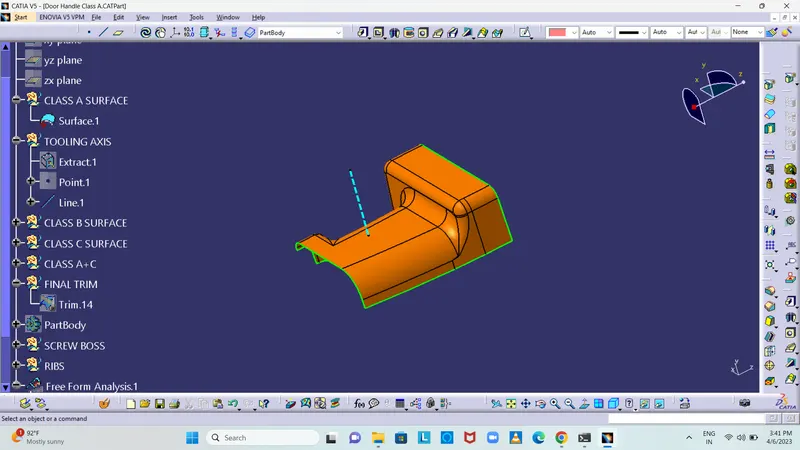
To create the tooling axis, I extracted the surface of class A with no propagation and I created the point at the centre of the extracted surface and created a line at that point in the Y direction. After creating the Tooling axis, I performed a draft analysis for class A to check the draft angle for it.
Class B surface Creation:
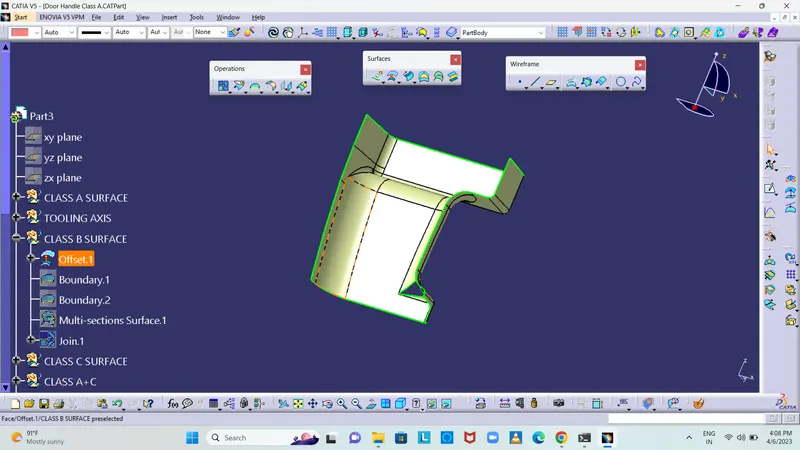
To create the class B surface for the door handle, I offset the class A surface to 2.5mm inside. Once the class A surface is offset created, according to the thickness, we can observe some patches on the offset surface due to the fillets on the class A surface. Now, we need to close those patches. I used multi-section solid command to close the patches.I observed only one patch on the offset, I used a multi-section solid command to close the patch to create the proper 'Class B surface'.
CLASS C SURFACE
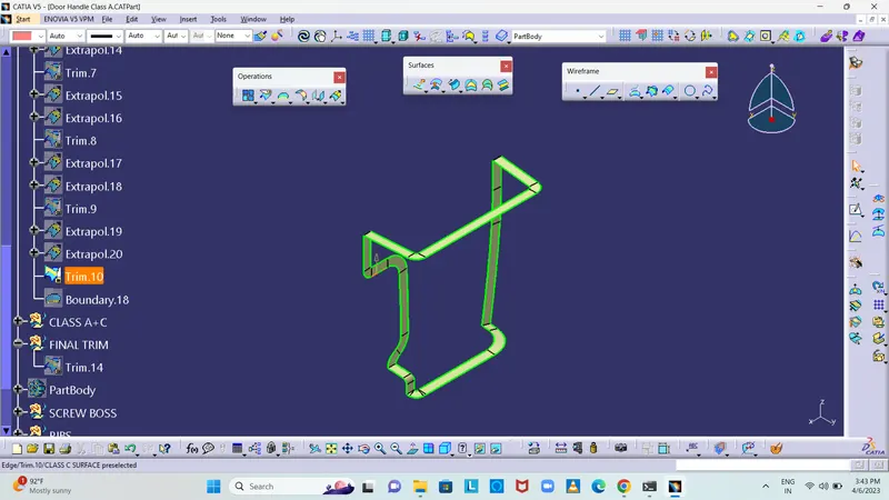
Extract the boundary from the class A surface using boundary command.Using disassemble tool to divide the boundary as the boundary contains domains.Use sweep command > choose profile type line > subtype as with draft direction > choose guide curve and draft direction > draft angle as 3 degree > preview.After getting sweep then trim the output with class B surface to get final output.Now open part design workbench and using close body surface create a solid of the component.
B SIDE FEATURES CREATION
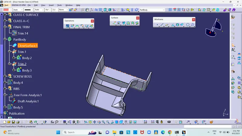
RIB CREATION:
Design Principle for Rib Creation
SCREW BOSS DESIGN
Design Principle for Screw Boss Creation
CONCLUSION:
The Tooling axis and the SolidCAT part with B Side Features is created from the given Class A Surface and Draft Analysis is Performed.