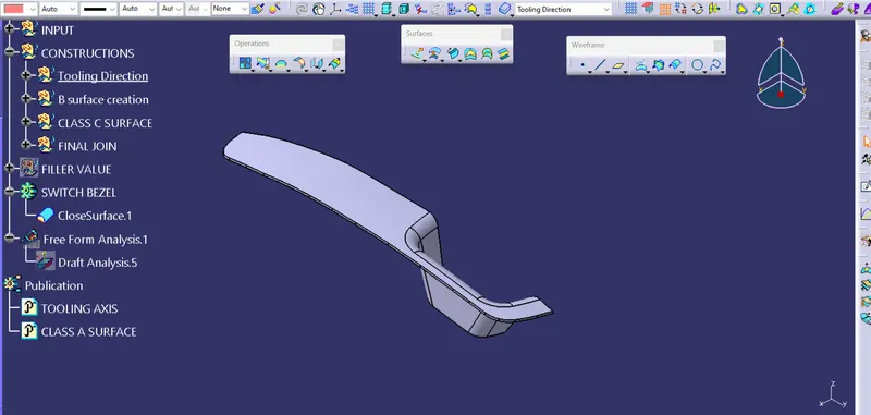
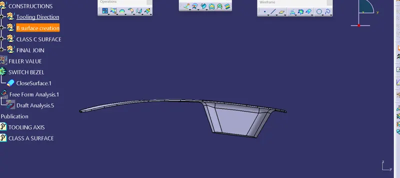
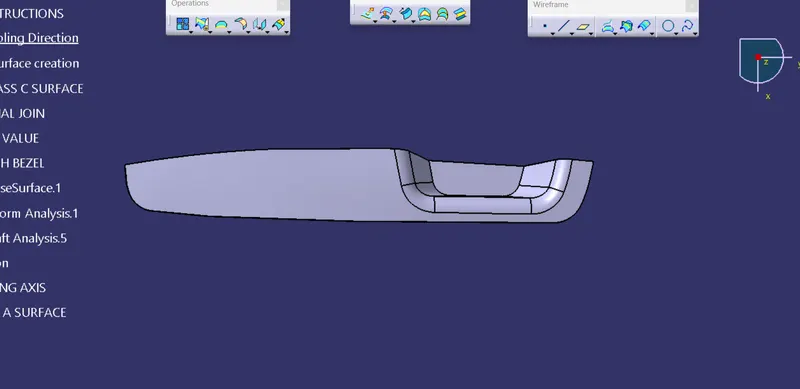
Week 8 - Challenge 2 - Switch Bezel Design
Features used for design A-Class, B-Class, and C-Class:
- Line
- Point
- Axis system
- Extrude
- untrim
- extrapolate
- Extract
- boundary
- Join
- Swept
- fillet
- close surface
- Intersecting
- Publication
Specifications:
- Base Bracket Thickness = 2.5mm
- Minimum Draft Angle = 3 Degrees
Class A Surface:
Class A surface is the term mainly used in automotive design industry. It describes
the final production surface data for the aesthetic parts of the car.
Tooling Axis Creation:
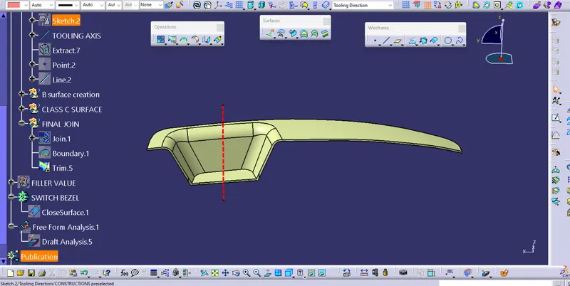
Using the intersection created lines will be created along the inclined walls, these lines are used for
creation of tooling axis by bisecting method where are two lines and point will be selected as inputs.
Creating intersection for checking along X-axis Using the tooling axis created along x-axis, these are used
for creation of tooling axis by bisecting method where the two lines and point will be selected as inputs.
Publication:
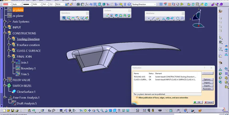
Publication is used to make easily accessible of the published components.
Class B surface:
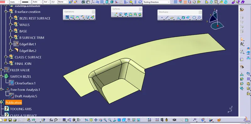
Class B surface is the secondary surfaces which is not visible normally.
These must be smooth and "error-free" as well, but are not held to the
standards that class A surfaces are.
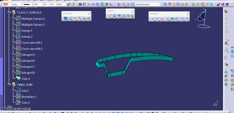
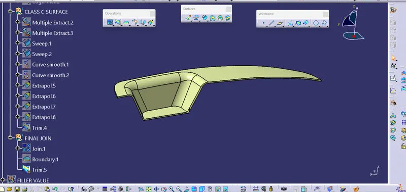
Class C Surface:
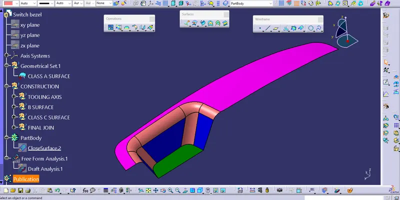
Draft Analysis:
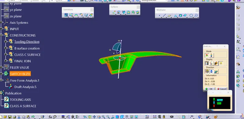
When the design is complete, draft analysis is done on the component.
After draft analysis is done we can observe that the green colour shows that the drafted walls of the
switch bezel are above 2.9 degrees which is a permissible cirteria to manufacture in injection moulding.
Close Surface:
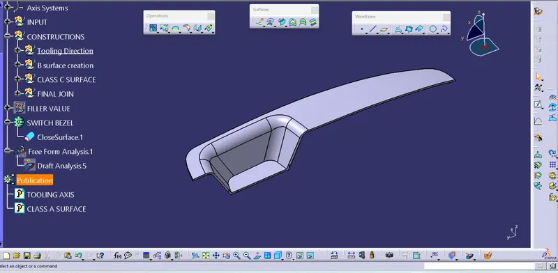
finally we got the close surface through the part design.
Conclusion:
1. Class A, Class B and Class C surfaces are created following standards of automotive industry using
Catia V5 software.
2. Draft analysis was performed on the switch bezel and it was observed that draft was under
permissible limit for the manufacturing of the component using injection moulding process.