Week 10 - Challenge 1- Attachment Feature Creation (Ribs & Screw Boss)
Design of DOOR HANDLE with the help of CATIA V5
*Objective:
* To design DOOR HANDLE with respect to the class a surface.
*Create class b surface and class c surface and the tooling Axis
*Convert those class A surfaces in a close body and make it into the solid body provide the thickness of 2.5 mm
*Performing draft analysis to verify the creation of tooling axis and class C surface.
* To create RIB and SCREEW BOSS
THE CLASS A SURFACE IS GIVEN....
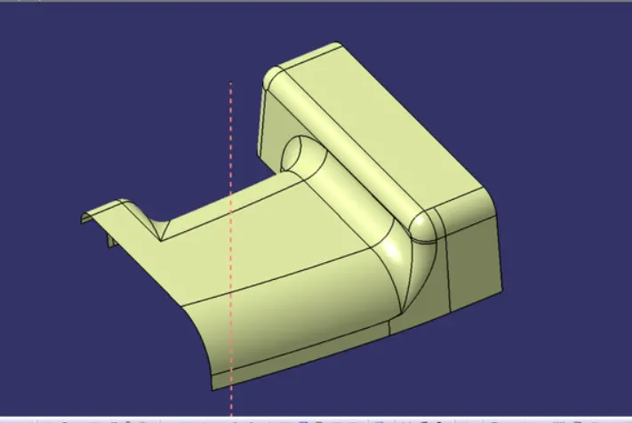
*Here we are using the software catia v5 generative safe design
.Design methodology with images
*How to create tooling axis….
-Create a point at the base OR any flat surface from where we can se max no. of surfaces from the class A surface.
-Extend the line at that point which is perpendicular to the plane or surface
Change the colour of that line and make it as construction geometry.
We can also use inertia method to create a tooling axis or bisecting method .
By creating all types of tooling axis still found there is some undercuts.
-Rename it as tooling axis.
HOW TO CREAT B SURAFCE OF THE DOOR HANDLE....
Select the whole class A surface and take an offset mode by 2.5mm at inside.
Now you can see some gaps are present in the offset surface….
You can fill those gaps by using multisection option, blend option or by extracting the class A Surface.
YOU CAN SEE THE GAPS AT THE OFFSET PORTION,
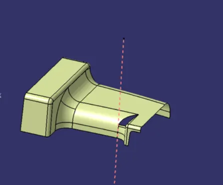
THE GAPS ARE FILLED
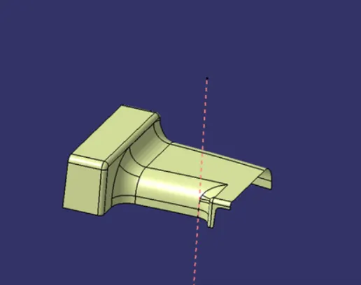
HOW TO CREATE CLASS C SURFACE…..
You can not allow to give direct sweep option by 90 degree in this case…
Because in this case there are more curved surfaces are available you can not direct extrapolate that surfaces.
So you have to take individually extrapolate that curved surfaces and flat surfaces by giving 90 degree + some draft angle.
HOW TO CREATE A CLOSED SURFACE
Join these Class C and Class A surface.
Now you can trim that joined surface and class B surface….
Now you have a close body of the DOOR HANDLE.
HOW TO CREATE A SOLID BODY….
You can make a solid body of the door hanldle by using that closed body….
Go through the part design> closed surface> select the closed body.
Now you have closed body of the bumper…
NOW JOIN THE B AND C SURFACES
JOINING OF A B C SURFACES..... YOU get the closed body..
and the solid body...
How TO APLLY DRAFT ANALYSIS…..
-Procedure of creating draft analysis
-Go to insert menu and select the analysis option
-Select feature and draft analysis
-Select the material option and select the surface
-Drag the compass and place on tooling axis
make sure that the top surface is in green colour as draft angles should not exceed 3 degree.
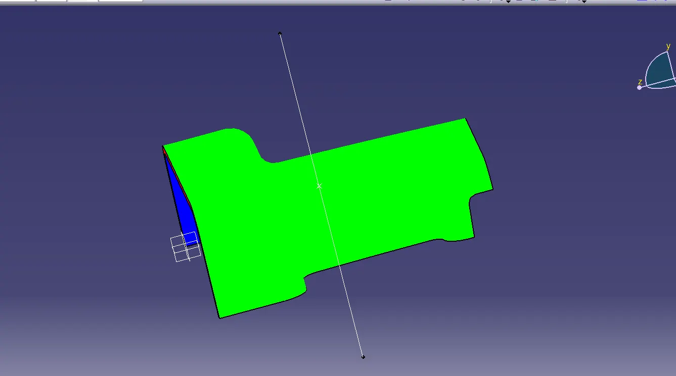
HOW TO CREATE RIB AND SCREEW BOSS BY USING THEIR DESIGN PROCEDURE
Design procedure of RIB….
*The thickness of rib must be 0.4 multiply by the thickness of the model which is 2.5mm.
*The space between the two rib is the twice of thickness.
*The fillet is must be 0.125* thickness or must be less then or equal to 0.25mm.
*THE height of the rib is must be the ratio of height and space between the two ribs
* The thickness at the top of rib is must be the less than or equal to 0.75mm
* Draft angle should be 0.5 degree per side of the rib.
DESIGN PROCEDURE OF THE SCREEW BOSS
Draft must be 0.5 degree at thw wall of the screw boss
Thickness typically 40% of the nominal wall at the boss.
TREE STRUCTURE
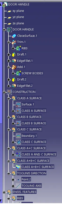
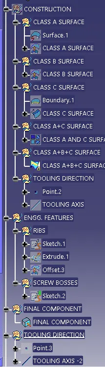
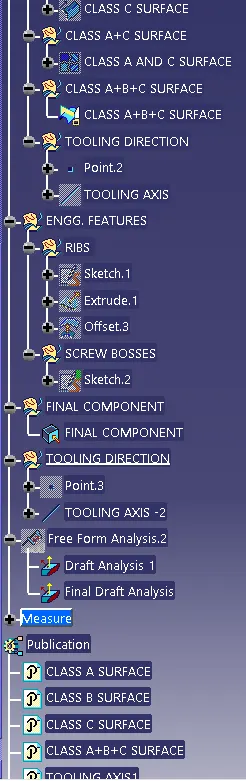
DRAFT ANALYSIS for the COMPONENT as follows :-
Draft analysis is done using featured draft analysis tool
Use the compass fucnction to align the compass to the tooling direction and lock the direction using lock function in the draft analysis tool bar.
the surface is showing green colour so that the surface clears the minimum draft angle of 3 degree and 0.5 deg on RIBS and SCREWBOSSES
By using the analyses under the running pointwe can check draft angle on the individual faces. It shows how much draft on specific points when we move the cursor point.
Green colour - above 3 degree positive draft
Red colour -between 3 and 0
blue colour- below 0 degree
Different views for draft colors are as follows :-
CONCLUSION
- Created the DOOR HANDLE component using the given Class-A surface.
- The tooling axis for the given Class-A Surface is created which meeting the requirements of the draft angle.
- Draft analysis is done on the CLASS-A surface.
- Class-B and Class-C surface is created.
- Using the Close Surface feature, Solid body is created from the surface.
- RIBS and SCREWBOSSES are designed as per design considerations.
- Draft analysis is done on the Final Component.