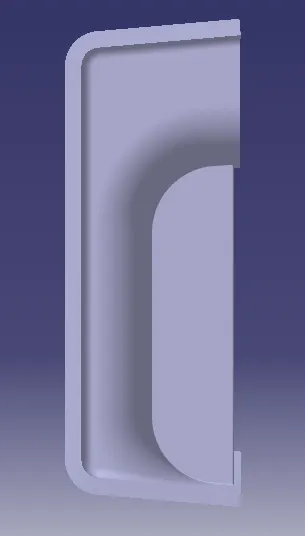
Week 10 - Challenge 1- Attachment Feature Creation (Ribs & Screw Boss)
A detailed report should be done explaining the draft analysis and the tooling axis creation.
What is draft analysis?
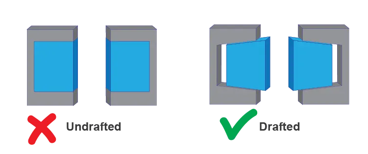
A draft analysis is used to see if the draft of a part is sufficient for the molding process and if the part will separate correctly from the mold. The draft refers to the angle between the face of a part and the direction of pull (refers to direction of the selected plane/face of a part) of each mold side.
Draft angles ?
A draft angle is calculated as a degree measurement (or, less often, an inch or millimeter measurement) from the vertical axis of a mold, and it helps account for thermoplastic shrinkage, a practical reality of the injection molding process for most materials.
TOOING DIRECTION ?
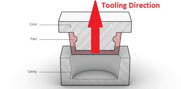
Tooling design is a specialized area of manufacturing engineering which comprises the analysis, planning, design, construction, and application of tools, methods, and procedures necessary to increase manufacturing productivity.
WHAT IS CLASS A, B, C SURFACES ?
Class A Surfaces
Class A surfaces are the highest quality surfaces and are typically found on the visible, outer parts of a product that end-users see. These surfaces require the highest level of finish and precision.Class A surfaces are free of any visible defects, imperfections, or blemishes. They have a flawless appearance with no visible waviness, distortion, or surface irregularities.These surfaces are often used for exterior car body panels, consumer electronics, and other products where aesthetics and appearance are critical.
Class B Surfaces:
Class B surfaces are of medium quality and are used for parts that are not directly visible to the end-user but are still visible when the product is disassembled or inspected closely.While Class B surfaces are not as critical in terms of appearance as Class A surfaces, they still need to meet certain quality standards and be free from major defects. Some minor imperfections may be acceptable.Examples of Class B surfaces can include the interior components of a car, where the surfaces are not as visible as the exterior but still need to have a reasonable level of finish.
Class C Surfaces:
Class C surfaces are the lowest quality surfaces and are typically used for parts that are entirely hidden from view once a product is assembled.These surfaces do not require a high level of finish or precision. They may have visible imperfections and may not be cosmetically appealing.Class C surfaces are often used for internal support structures, functional components, or parts that are concealed within a product and do not affect its appearance.
An explanation should be given on the way of creating the tooling axis, particularly the Bisecting methodThe best direction for Class A surface inspection is the largest direction seen from the normal angle. Then subtract the area, create a point and create a line.
Sketches
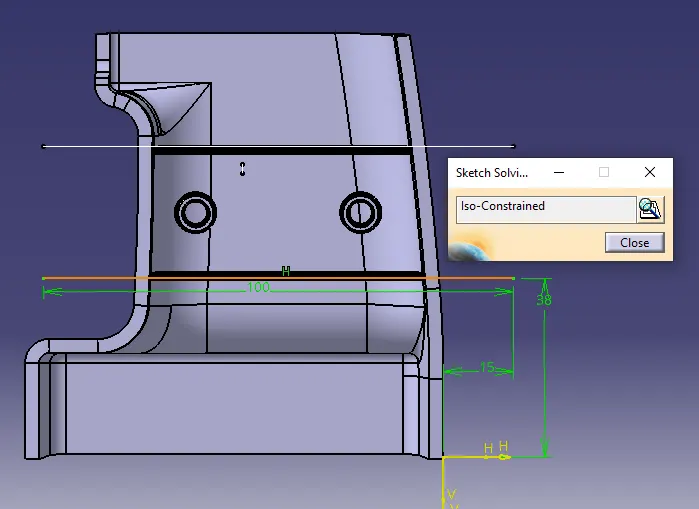
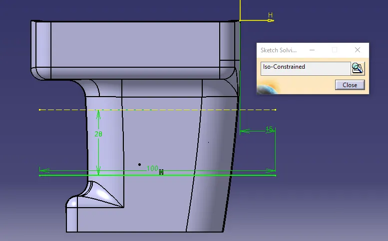
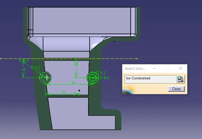
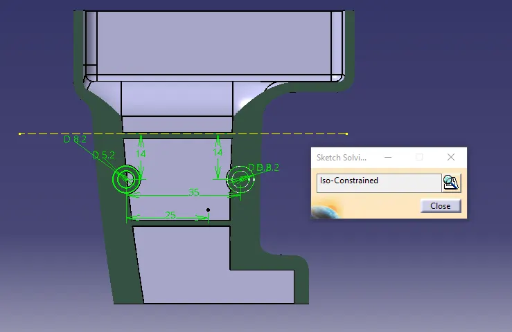
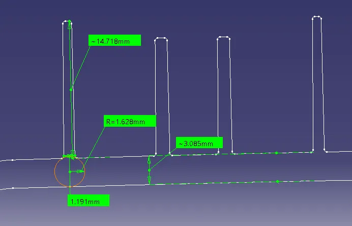
An explanation should be given on the way of creating the tooling axis, particularly the Bisecting method.
Determining the Optimal Direction for Maximum Edge Visibility in Class A Surface Inspection When inspecting a Class A surface, it is essential to identify the best viewing direction to maximize the visibility of edges from a normal perspective. Once this direction is established, we can proceed to extract the surface of interest, create a reference point, and generate a corresponding line.
Screenshots of the Draft analysis report for both the given Class-A surface and the final plastic component
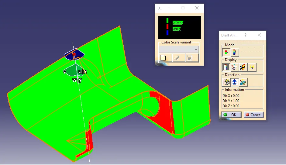
The initial analysis is conducted on the Class A surface to determine the accuracy of the tooling axis. In this analysis, areas appearing in green indicate a draft angle of 3 degrees or more, which signifies that the tooling axis is correct. Conversely, regions marked in red indicate draft angles less than 3 degrees." Please let me know if you need any further assistance or if you have any more content to be checked for plagiarism.
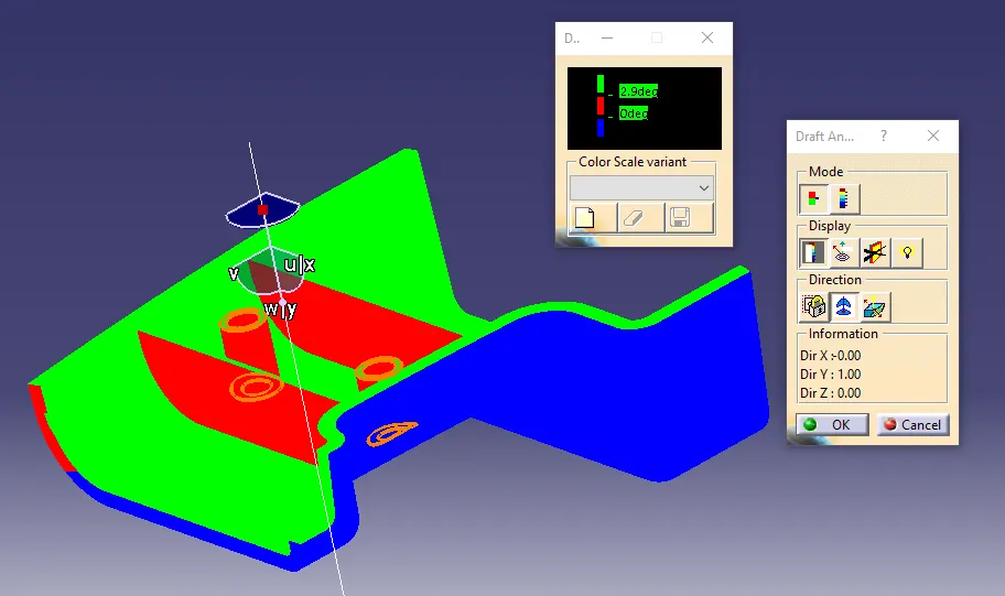
"The second draft analysis is performed on the solid body, where areas displayed in green signify a draft angle of 3 degrees or more. This indicates the correct draft angle for the solid body. In contrast, the blue color indicates a negative draft angle, which is a requirement for the base side of the solid body. There are also some red portions observed on surface 'A' in certain areas. These red lines represent fillets, which are considered acceptable. In cases where the draft angle is 2.9 degrees, some areas may appear green, which is also acceptable. The presence of red color is primarily attributed to the vertical portions." If you have any further questions or need additional assistance, please feel free to ask.
"Along the edges, the presence of a blue color indicates a negative draft angle, which is not desired. To address this issue, I employed a spline and subsequently created a multisection at the corner. In an attempt to rectify the problem, I used a sweep command with a 100-degree angle concerning the draft angle when creating the 'C' surface. However, it still appears in blue." If you have any further questions or need additional assistance, please let me know.
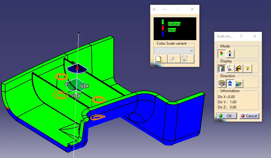
"I assigned a positive draft angle of 0.45 degrees to both the boss and the rib."
Screenshots of the completed design in various orientations (Isometric, Front, Side, and Top View)
Isometric
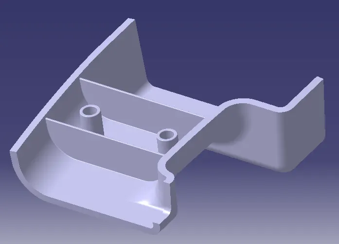
Front
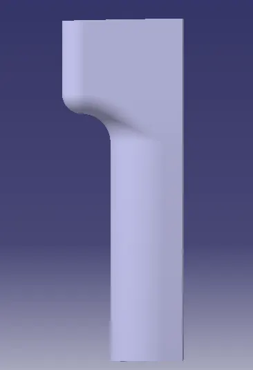
Side
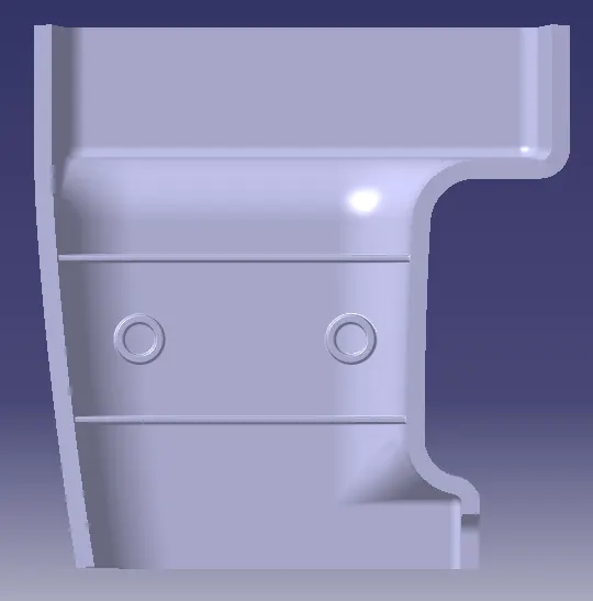
Top View