Week 10 - Challenge 1- Attachment Feature Creation (Ribs & Screw Boss)
AIM:-
To Create the rib for the Drill Handle & Screw boss considering the design rules mentioned in the video.
DESCRIPTION:-
- Used Positioned sketch.
- Sketches are Iso-Constrained.
- Ensured Proper Tree Structure.
- Geometrical sets had a proper name based on the sketches present inside of it.
- All the sketches are created under the Geometrical set.
- Thickness of the component is 2.5mm.
TOOLING AXIS:-
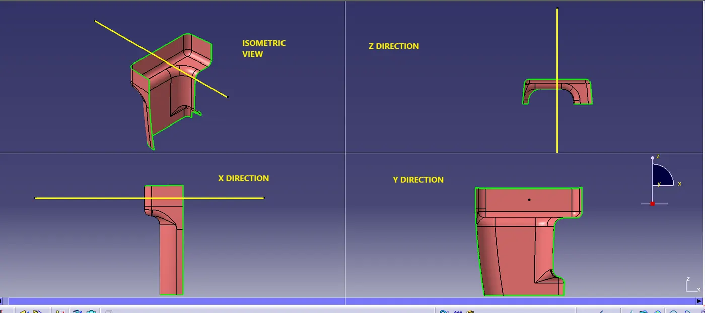
The above image shows all the axis directions in that Y axis direction is more feasible for the tooling axis. Most of the surfaces are visible in that axis. The tooling axis was created using Bisecting method.
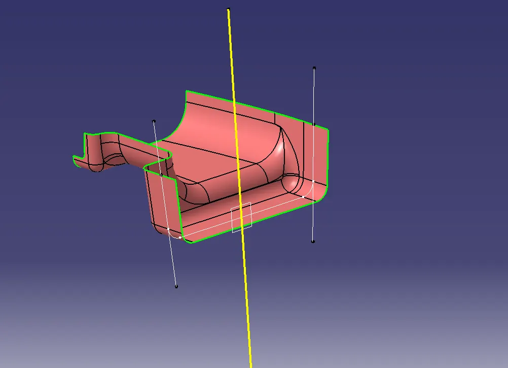
DRAFT ANALYSIS:-
For Draft analysis more tooling axis created for this drill handle to check the given class A is clearing draft analysis or not . The given class A is not clearing the draft analysis even creating multiple tooling axis for the given class A.
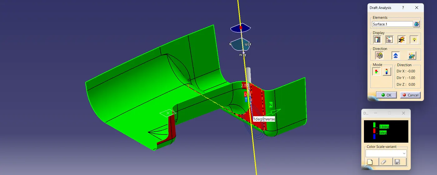
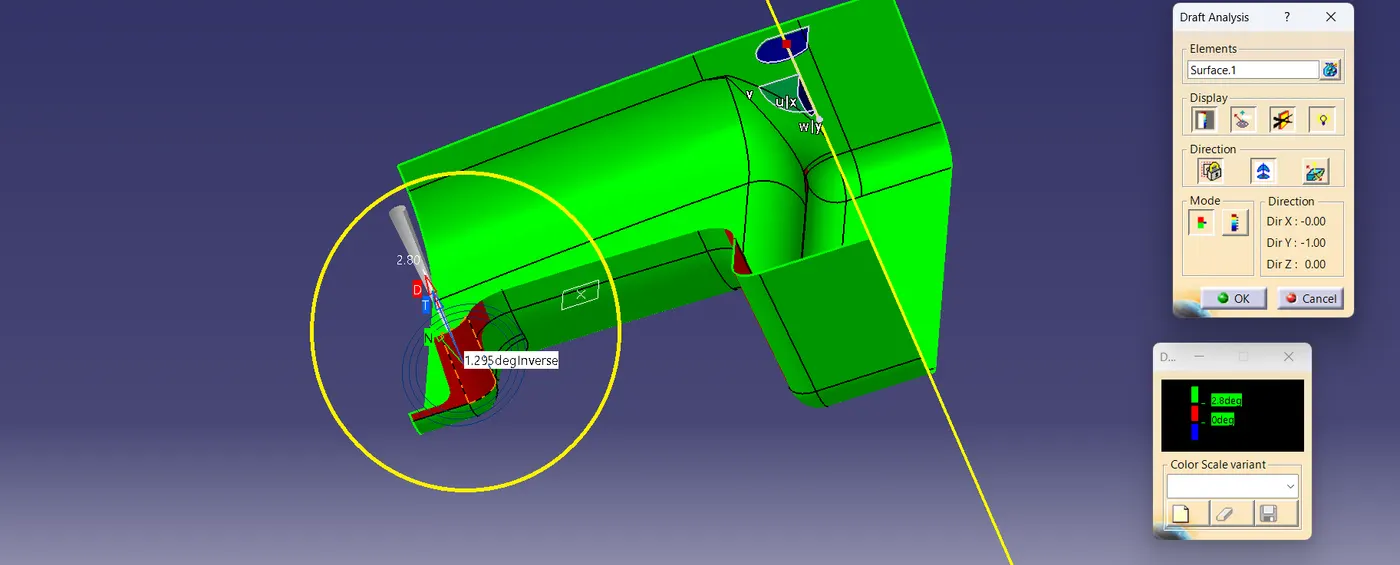
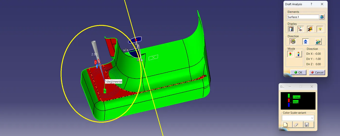
These Class A surfaces are having less than 2.8deg of draft angle.
DRAFT ANALYSIS OF THE SOLID BODY OF DRILL HANDLE:-
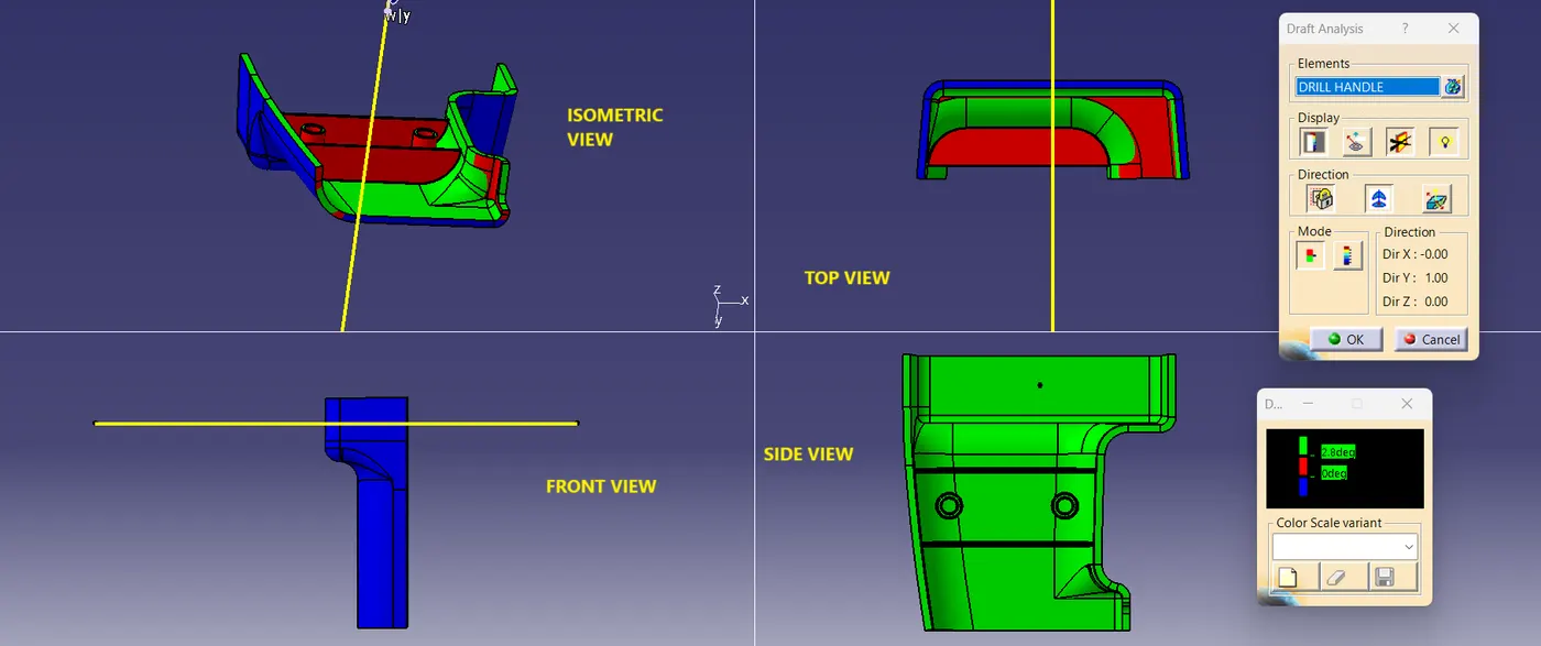
Due to the given class A surface & in draft analysis were some surfaces are not cleared nominal 3deg draft. In class B surface also the same condition. In class C surface perpendicular to tooling axis will be created with reference surface and 90deg draft sweep. C surfaces which are parallel to tooling axis will be created with draft direction 3deg draft sweep. The connecting corner C surfaces are created using multisection surface with the help of boundary and spline of the respected two support surfaces.
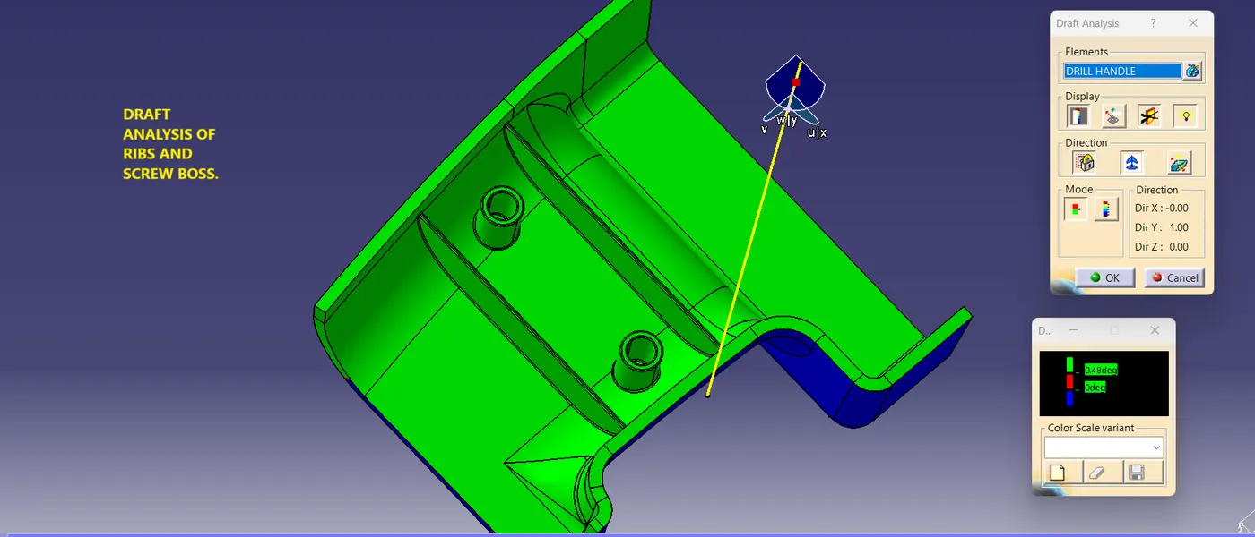
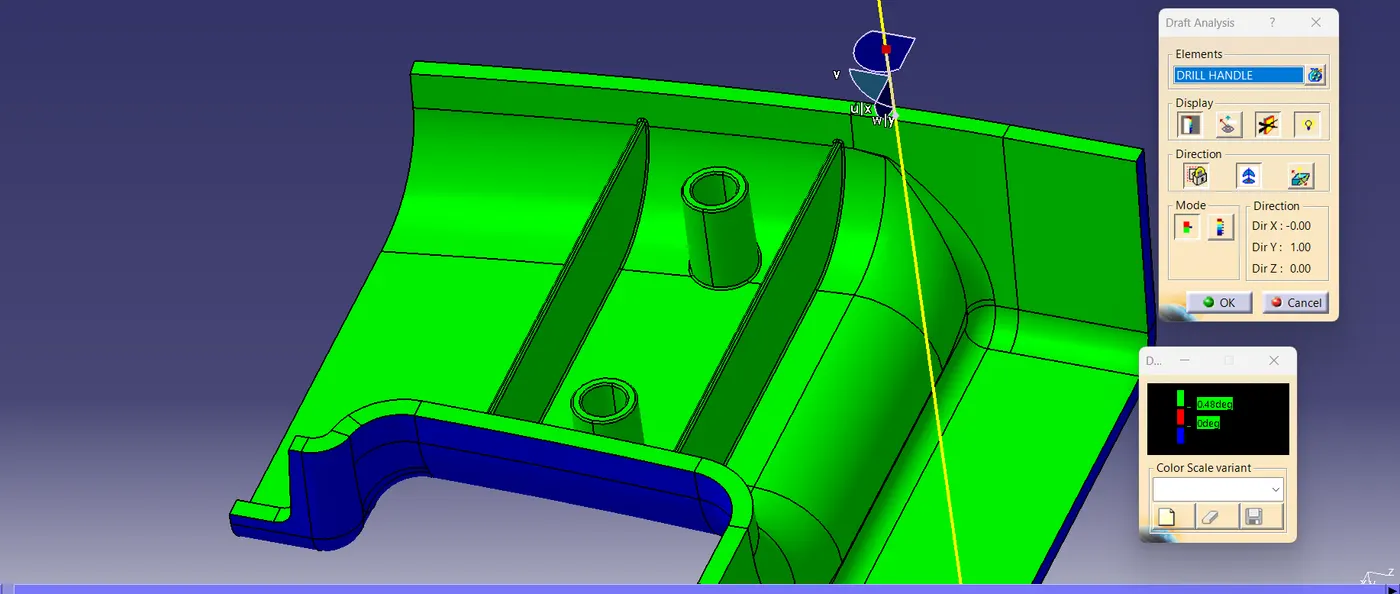
DRAFT ANALYSIS OF RIBS & SCREW BOSS OF DRILL HANDLE:-
RIBS AND SCREW BOSS WERE CREATED WITH RESPECT TO THE DESIGN RULES MENTIONED IN THE VIDEO.
General Guidelines for Ribs:-
- Draft - 0.5 degrees on the walls of Ribs
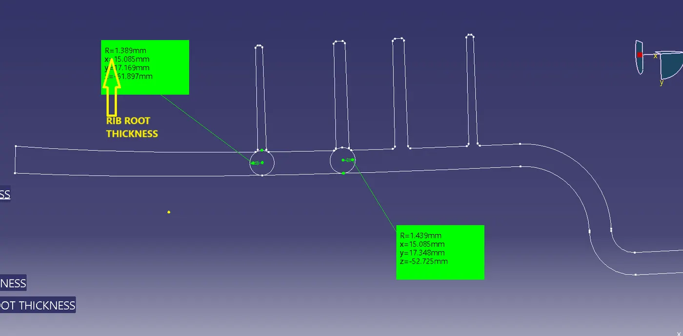
- Thickness - Typically 40-60%* of the nominal wall at the base.
- Height -5*t
- Radii - 0.25mm maximum radii.
RIB ROOT THICKNESS ANALYSIS:-
General Guidelines for Screw Bosses:-
- Draft - 0.5 degrees on the walls of boss.
- Thickness - Typically 40-60%*t of the nominal wall at the base.
- Radii - 0.25mm maximum radii.
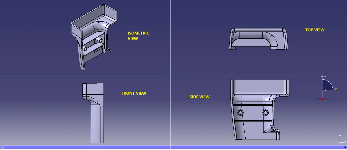
Screenshots of the completed design in various orientations (Isometric, Front, Side, and Top View):-
TREE STRUCTURE:-
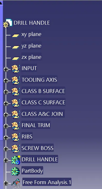
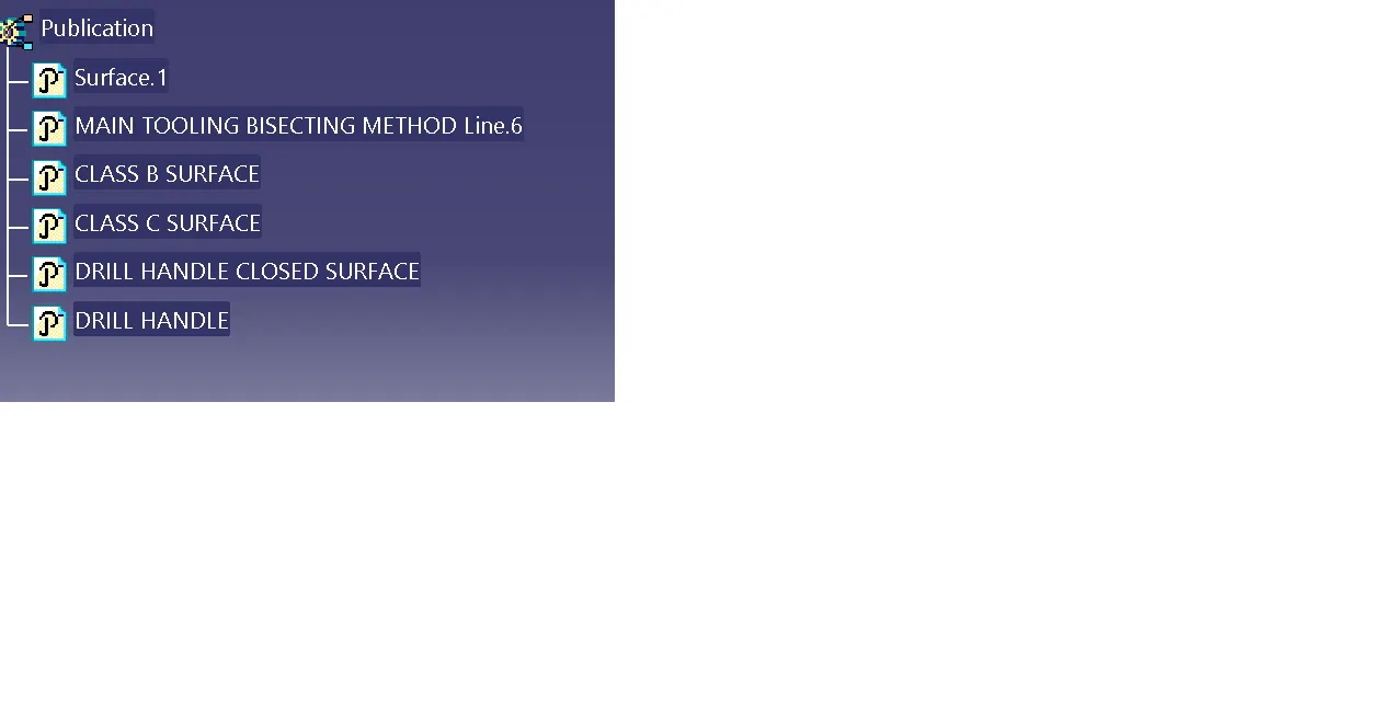
PUBLICATIONS:-