Week 10 - Challenge 1- Attachment Feature Creation (Ribs & Screw Boss)
CHALLENGE 1
DESIGN OF RIBS AND SCREW BOSS
AIM: To create the rib and screw boss for the Drill Handle considering the design rules mentioned in the challenge
Design the Ribs and Screw boss for the given drill handle as per the design rules and follow the steps as for the given class A.
- TOOLING AXIS
- DRAFT ANALYSIS
- CLASS B
- CLASS C
- FINAL DRILL HANDLE
- CREATION OF RIBS AND SCREW BOSS
Given class A component is
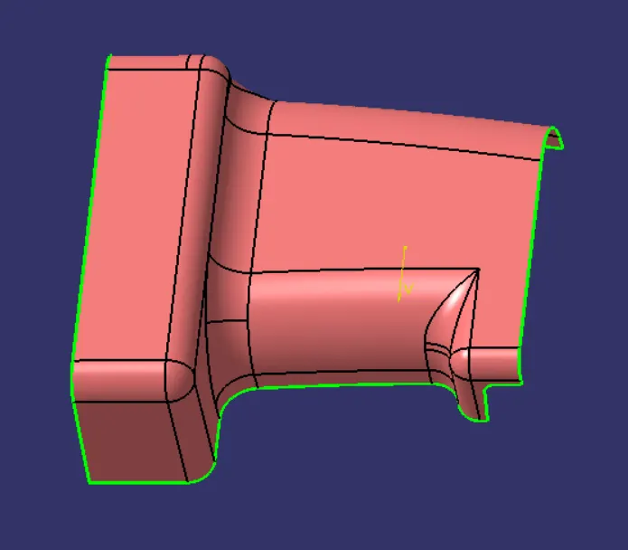
For the class A surface create a tooling axis.
TOOLING AXIS:
Tooling axis is the direction in which the core and cavity opens in the tooling direction.
- Extract one flat surface, create a point and then create a line normal to the extracted surface.
- Created line is the tooling axis for the drill handle
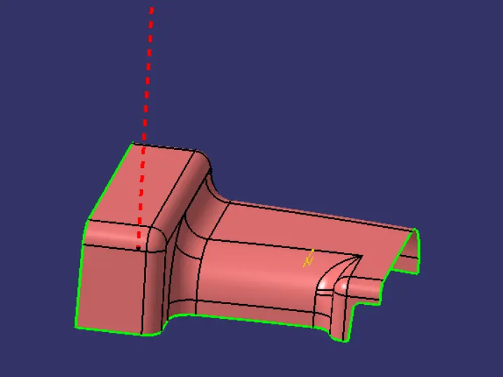
- Next is to perform the draft analysis.
DRAFT ANALYSIS:
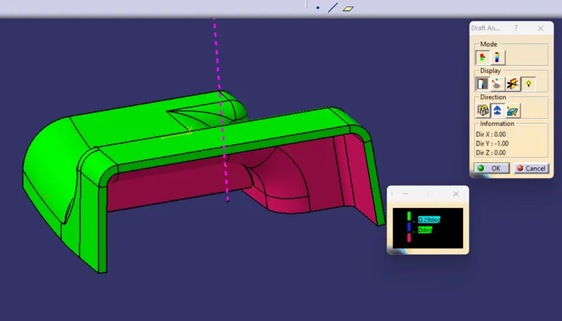
Draft analysis technique is used to analyse the whether our part model created in CAD is manufacturable based the draft condition applied.
- First go with the draft analysis command and place the compass at the tooling axis and click the compass option in the draft analysis table.
- Click on the component and some colour changes in the component.
- Change the angle to 0.5 deg for the draft.
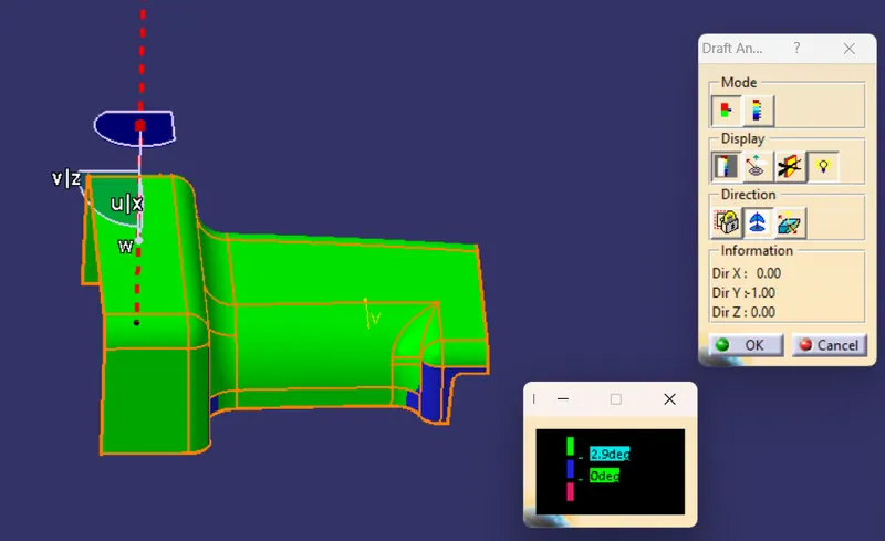
- This is the draft analysis for the given component.
CLASS B:
- create the class B surface by offset the Class A to 2.5mm
- extract all the surfaces except the edges and extrapolate them.
- Trim the all surface after extrapolate them
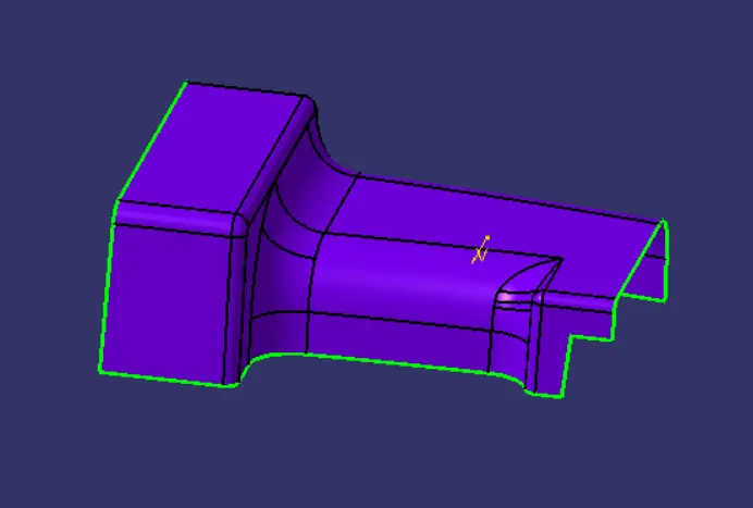
- Final creation of Class B is done and next is to create class B
CLASS C:
- Create a boundary for class A.
- Create a C surface using sweep command with reference surface
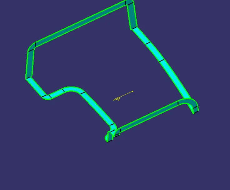
FINAL DRILL HANDLE:
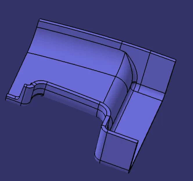
RIBS AND SCREW BOSS:
- To design a RIB for a component we should fallow some design rules
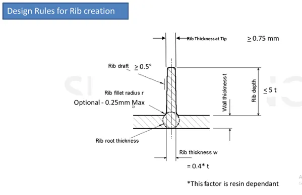
- The above image is specify the design rules of a rib
- The nominal thickness of the component is 2.5mm
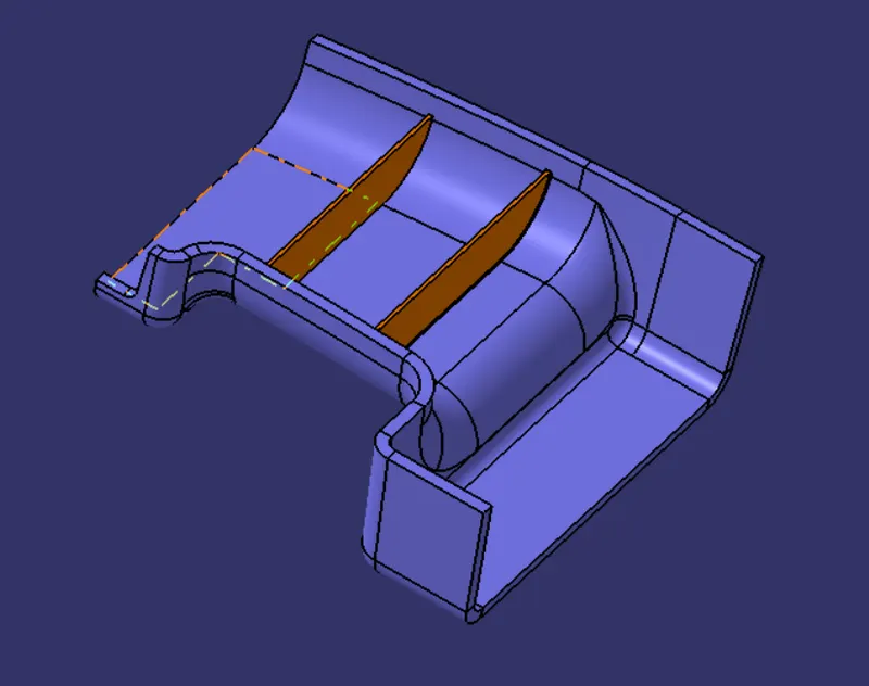
- Ribs is created and next is to create the screw boss
- The design rules for the screw boss is given in the below image
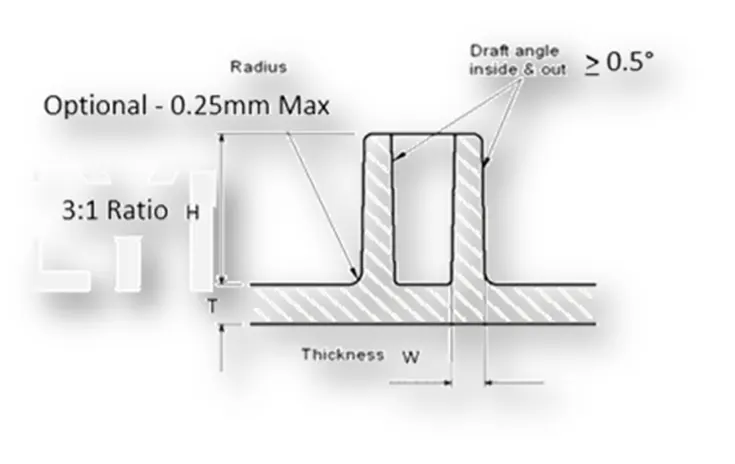
- Draft - 0.5 degrees on the walls of boss
- Thickness - Typically 40%* of the nominal wall at the base.
- Height to Diameter Ratio - 3:1
- Radii - 0.25mm maximum radii.
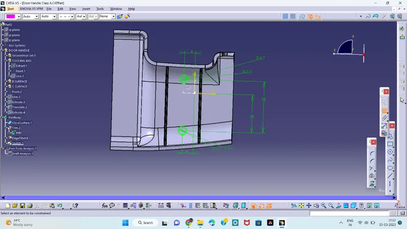
- Create a M6 screw for the component as per the given rules.
- Create a new body and pad them.
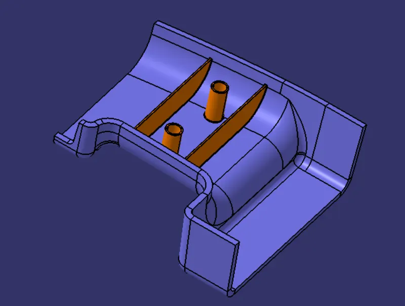
- Ribs and Screw boss is designed as per the given rules.
- Check again draft analysis the design component is correct or not.
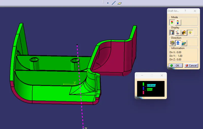
all engineering feature ,class A, class b, class C surface are clearing in draft analysis.