Week 10 - Challenge 1- Attachment Feature Creation (Ribs & Screw Boss)
AIM:
The main objective of this challenge is to create the B-side features Ribs and Screw bosses for the given drill handle.
RIBS AND SCREW BOSSES
TOOLING AXIS:
To create the tooling axis first a surface is extracted from a class-A and then a point is created at the centre of the surface by using the point command then using the line command line is created along the Y-axis and at last Draft Analysis is performed to check whether the component is able to manufacture or not.
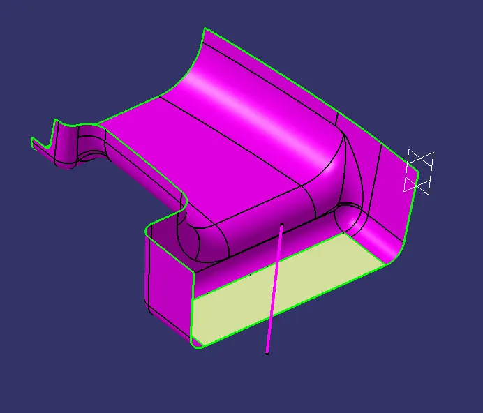
DRAFT ANALYSIS OF THE CLASS-A SURFACE
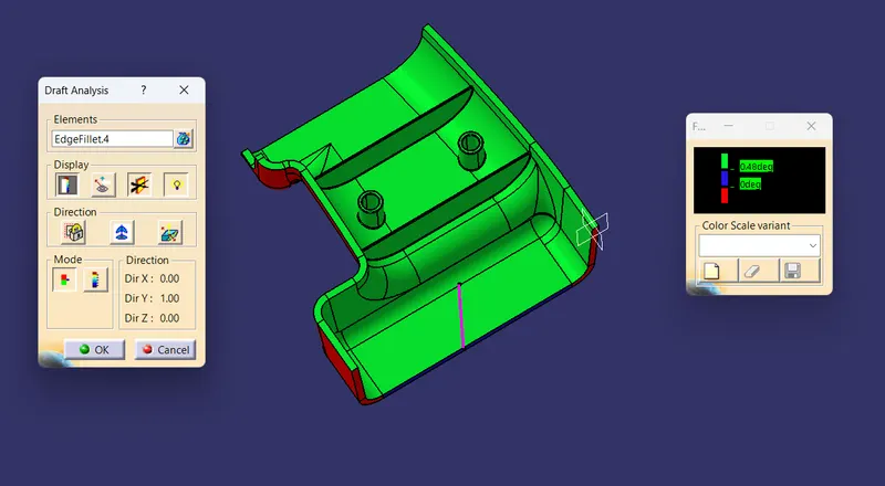
Draft analysis of the surface is done by using the Draft analysis Command in the Generative shape design in that I will select the Class-A surface and enter the required Angle to clear the Draft analysis.
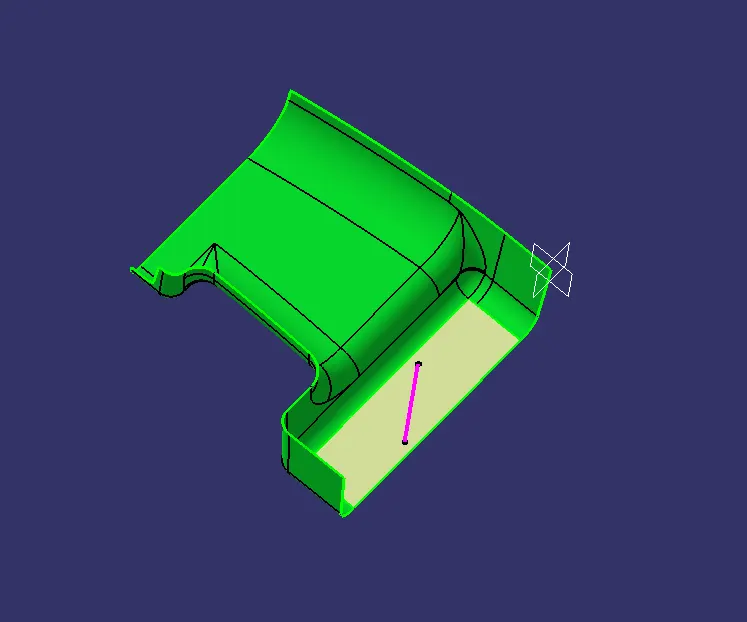
CLASS-B SURFACE CREATION
Class-B surface is created by offsetting the class-A surface by 2.5mm. and the edges of the class-B surface are extrapolated for trimming with the class-C surface
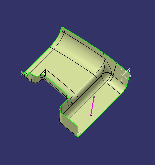
CLASS-C SURFACE
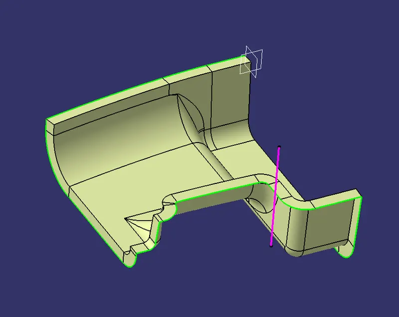
Class-C surface is created by using the Sweep command in the Generative shape design workbench to create the class-C surface then class-A surface with the tangent continuity by using the boundary command and then sweep as been done for 5mm to intersect with the class-B surface now trimmed the sweep surface to create the class-A & C surface and at last, I joined the class-A & C and then by using these surface I trimmed the class-B surface to create the closed surface.
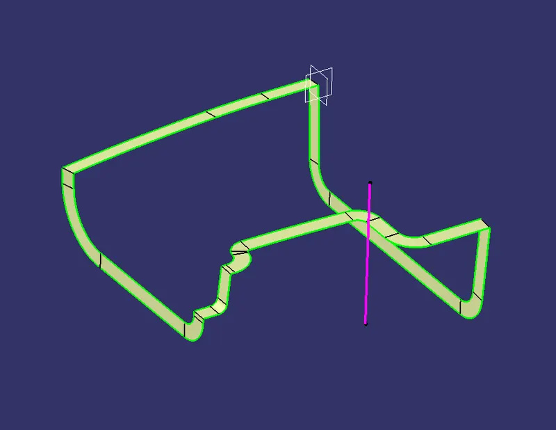
CLASS A&C SURFACE:
CLOSED BODY
SOLID-BODY
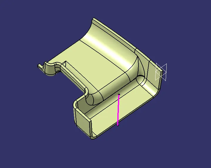
To create the solid body I used the closed surface command in the part design workbench and the solid body is created
RIB DESIGN
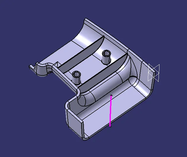
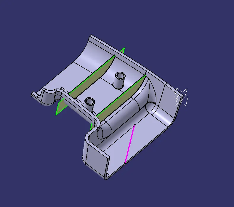
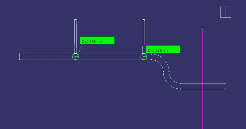
To create the rib design we need to follow the above-mentioned design guidelines initially creating a line in the sketch and then extruding along the direction of the tooling axis then thickness has given after that union trim is done to remove the excess material to ensure the easy removal the minimum draft angle 0.50 is given and 0.25 mm of minimum radius given to remove the sharp edges.the same step is followed for rib 2.
SCREW BOSS
DRAFT ANALYSIS OF THE FINAL COMPONENT
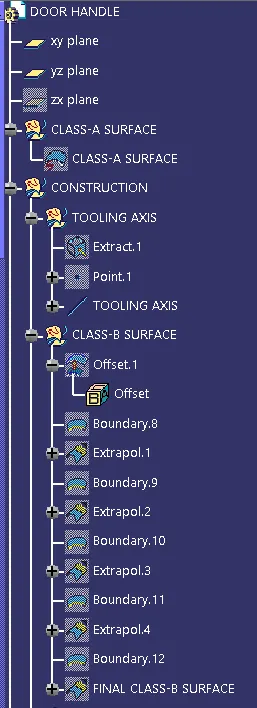
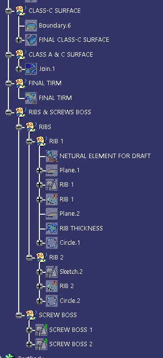
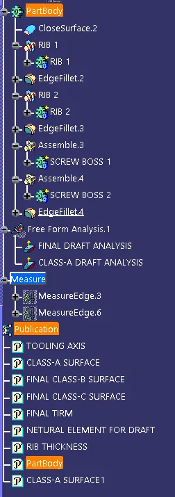
TREE STRUCTURE
CONCLUSION
the above part is created with all the design requirements and all the steps as been followed to achieve the final part.