Week 10 - Challenge 1- Attachment Feature Creation (Ribs & Screw Boss)
Create the component through the given Class-A surface.
the tooling axis for the given Class-A Surface should be created meeting the requirements of the draft angle and at the end perform the Draft analysis on the model. Create the rib and screw boss as by considering the design rules
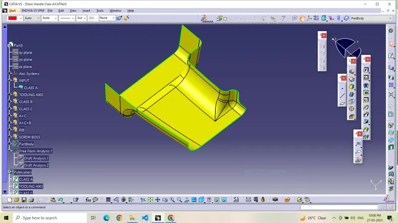
CLASS A SURFACE:
CREATING TOOLING AXIS :
TOOLING AXIS Also created by bisecting the axis created on two intersections.
Flat surface on the center part is extracted for creating the tooling axis in y direction
Then created a with the point and direction along y axis.
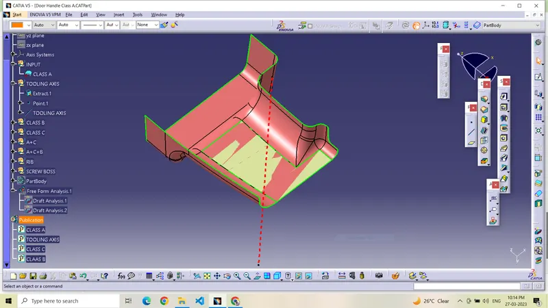
DRAFT ANALYSIS OF CLASS A SURFACE:
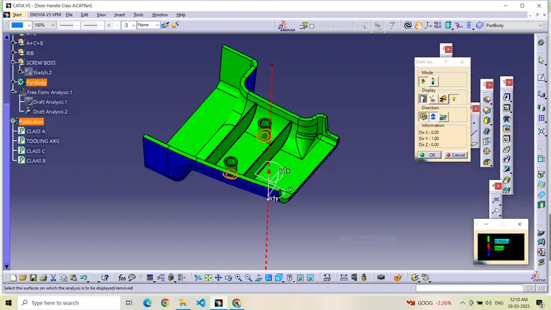
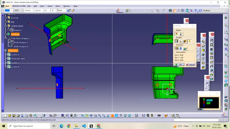
draft analysis is done using featured draft analysis tool.
Use the compass fucnction to aling the compass to the tooling direction and lock the direction using lock function in the draft analysis tool bar
the surface is showing green colour so that the surface clears the minimum draft angle of 3 degree
By using the analyses under the running pointwe can check draft angle on the individual faces. It shows how much draft on specific points when we move the cursor point.
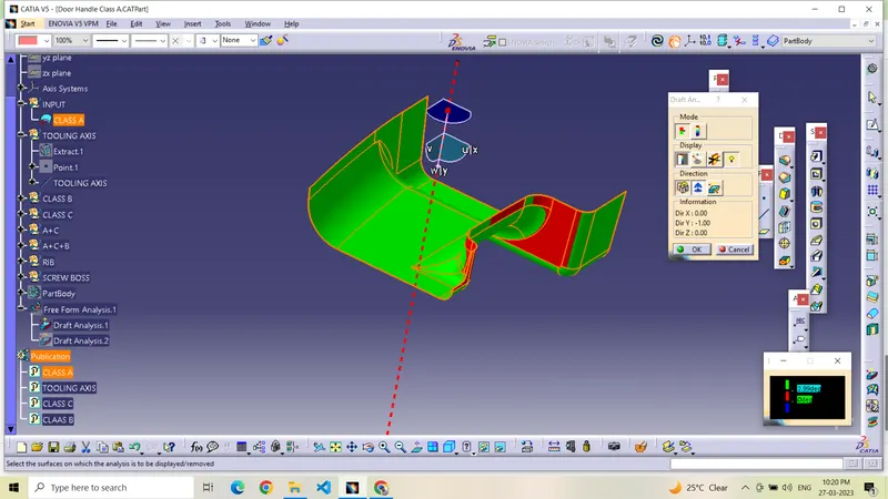
in the above image we can see clearly the red marks that means it is clearing the draft angle at 3 deg so we can change to 0.5 deg then it will clear shown below
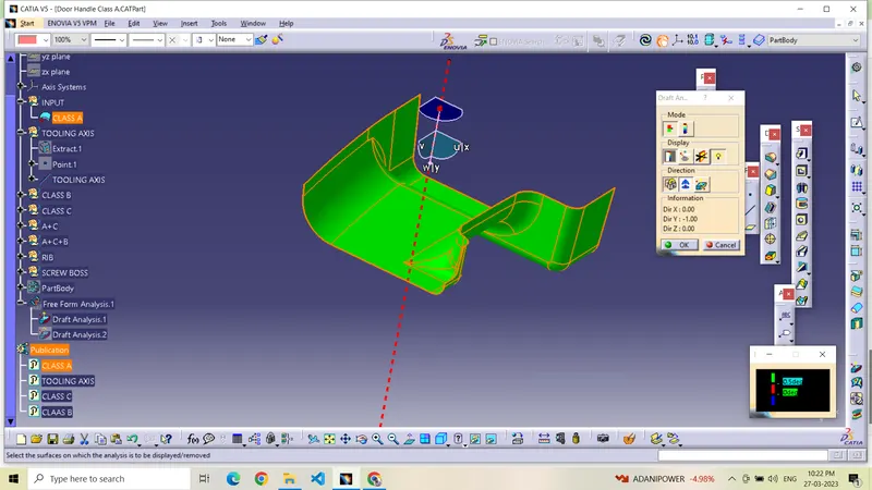
from the above image we can see that the your tooling axis is clearig the all draft angle with 0.5deg, so that we can proceed for the next operations otherwise we have to cxhange the tooling axis
next generating the surface-b
here we have the thickness of 2.5mm, so we have to take the offset of 2.5 mm the offset surface is shown below
offset
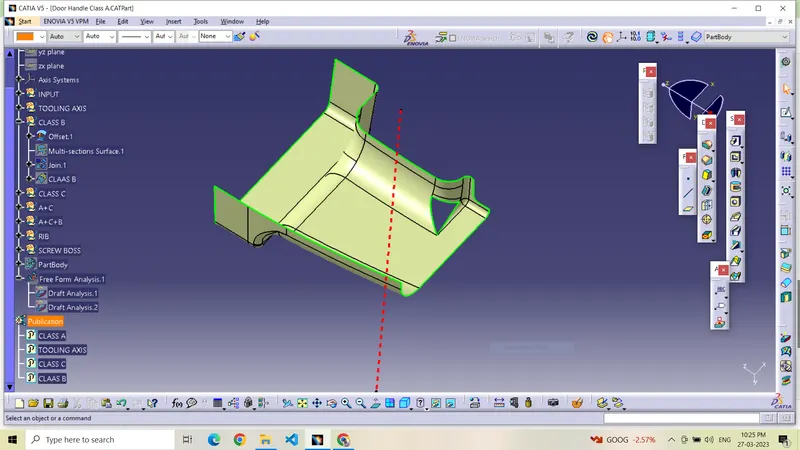
when we have offset the surface the we got thesome patches missing then we have to filling these patche highlighted using some commands as in part file
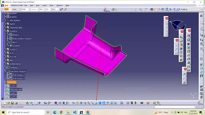
CREATING CLASS C SURFACE:
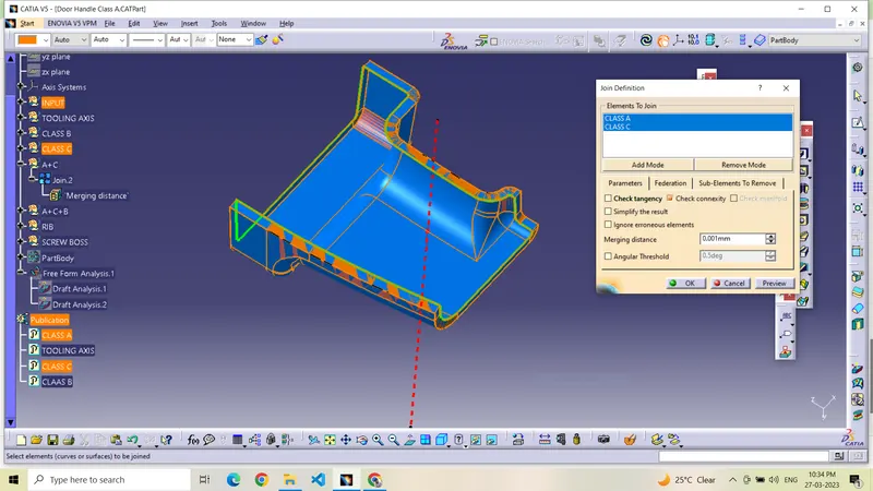
now we have to create the c-surface from the class-a surface by using the sweep command at 90 degrees from the class-a surface and join the class-a and class
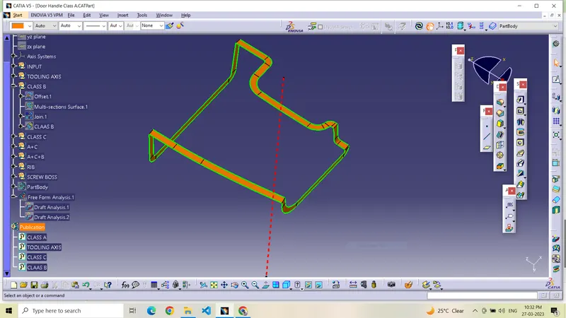
CLASS A and CLASS C is JOIN together
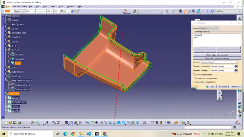
CLASS B is trimmed with CLASS A AND C
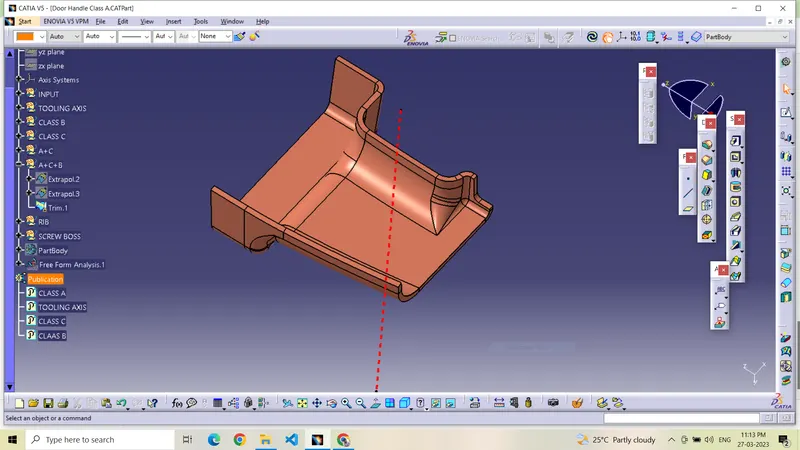
SOLID SURFACE FORMED
sketch is created for ribs
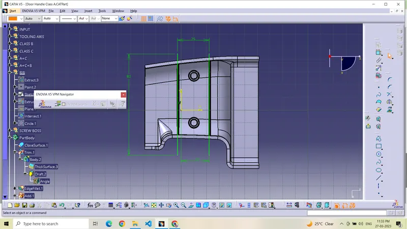
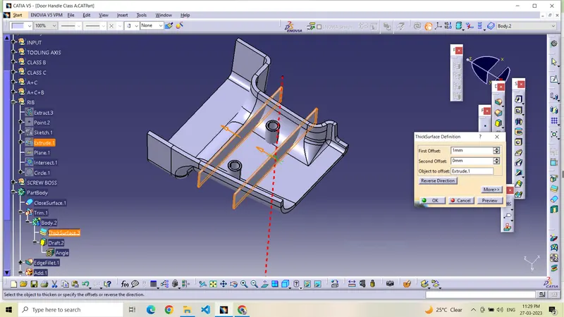
height - <=5t (thickness of part)=2.5*5 =12.5
thickness = 0.4t (thickness of part) =0.5*2.5=1
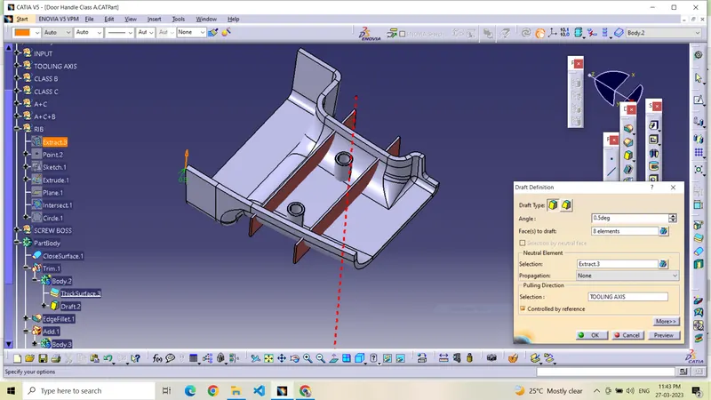
RIB DRAFT 0.5DEGREE
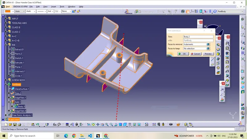
TRIM THE UNNECCESSARY EDGES
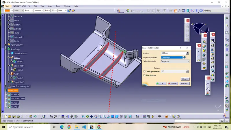
CREATING SCREW BOSS
the outer diameter
Thickness - Typically 40%* of the nominal wall at the base in one side
40% of 2.5 =1 mm one side =7.2
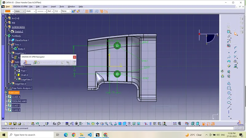
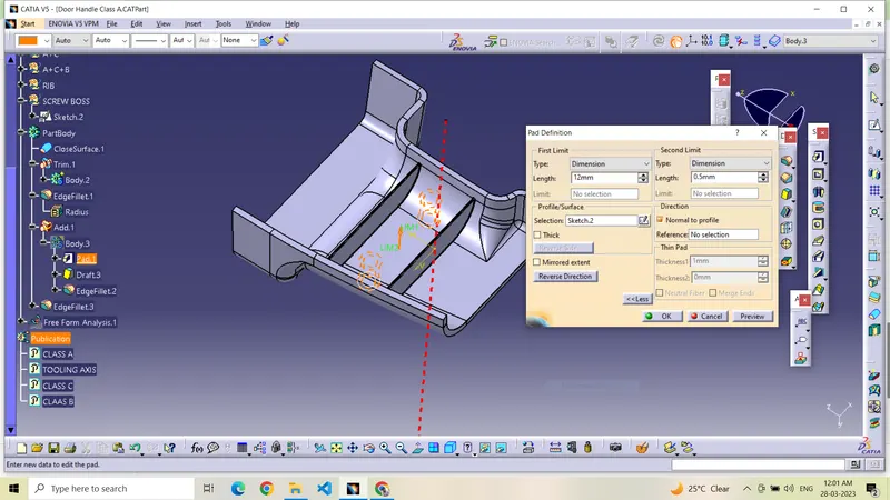
paded the sketch for height
Height to Diameter Ratio - 3:1
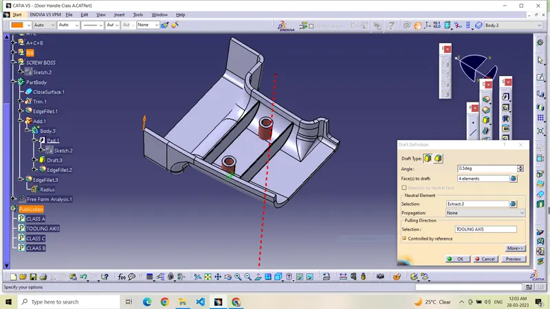
Draft - 0.5 degrees on the walls of boss
Radii - 0.25mm maximum radii.
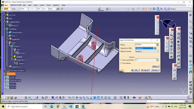
FINAL COMPONENT
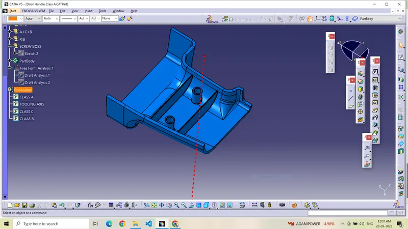
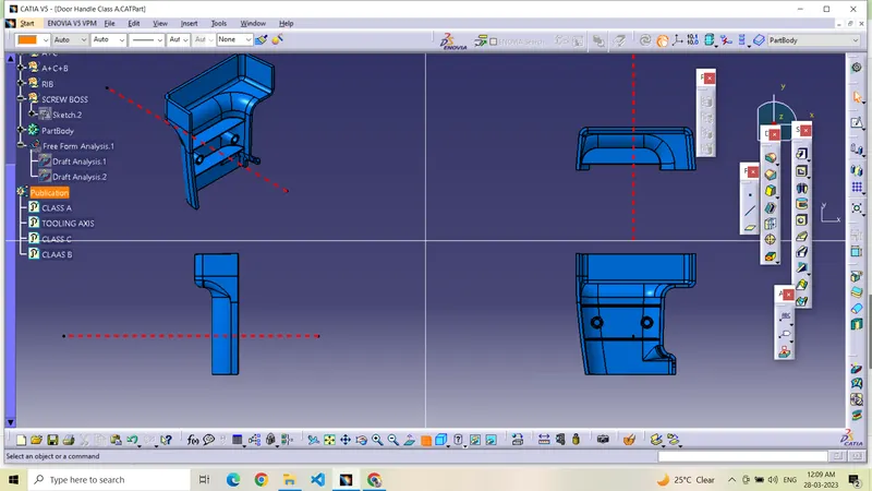
DRAFT ANALYSISOF COMPONENT