Week 10 - Challenge 1- Attachment Feature Creation (Ribs & Screw Boss)
Door Handle (Rib & Screw Boss Attatchment)
Aim -
- To create the Door Handle Component from the given Class-A surface.
- To attach B side features, ribs and screw bosses,in the component.
- To perform the Draft analysis on the model.
Take the thickness of the component to be 2.5mm.
Design Procedure (Door Handle) -
- Check the Class A surface for discontinuities. Create a suitable tooling axis with a flat surface as reference.
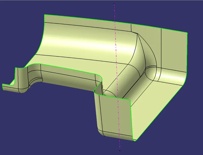
- Offset the Class A surface by 2.5mm inwardsa to get the Class B surface.
- Check for discontinuities on the Class B Surface, repair the surface if errors are found.
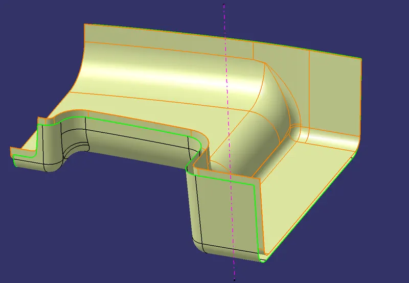
- Create the Class C surface with the sweep operator.
- Use the draft axis as the reference for the swept surfaces parallel to the draft axis.
- Use the Class A surface as the reference for the swept surfaces perpendicular to the draft axis.
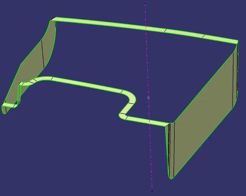
- Join the Class A and C surfaces. Extrapolate the Class B surface so that it intersects with the Class A&C join.
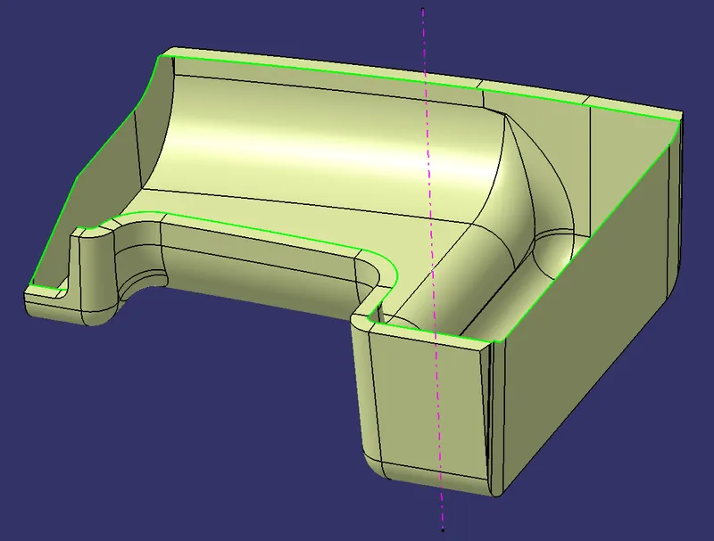
- Trim the Class A&C join with the Class B surface to get the hollow closed surface.
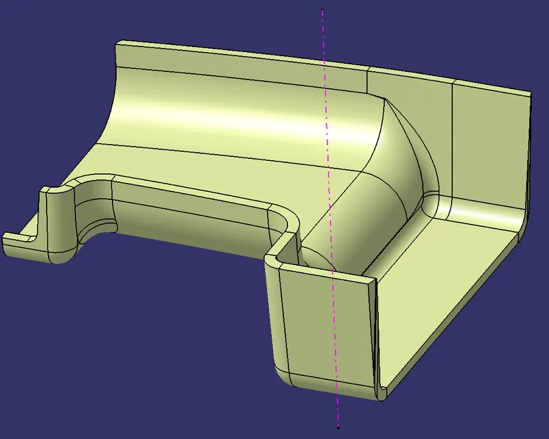
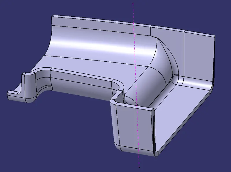
- Use the close surface command in part workbench to create the solid part body of the Door Handle.
Design Procedure (Ribs) -
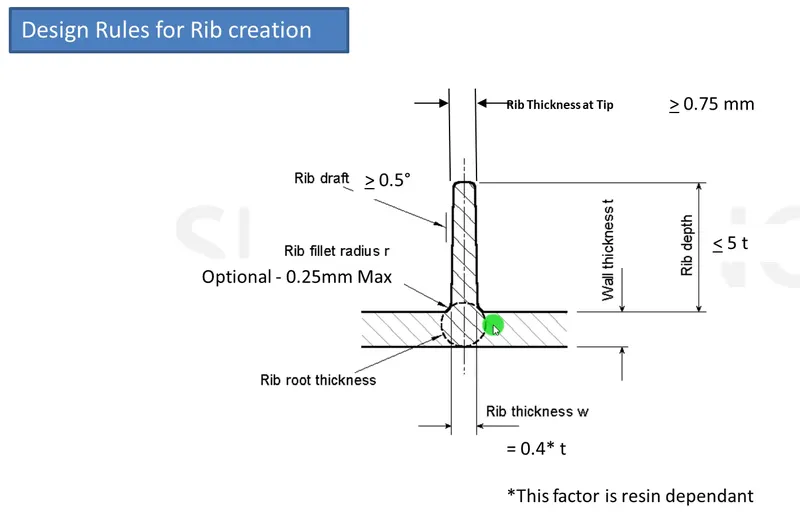
Ribs are thin extensions that run perpendicular to a surface from the wall of the component. They are used to provide additional support and strength to the part.
- Create an iso-constrained sketch on the surface/ plane on which the rib will be constructed.
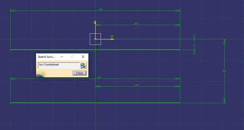
- Add a new Body and Pad the Sketch to for the rib’s profile.
- Add a draft of 0.5deg to all the required surfaces.
- Create the required number of ribs in a similar way or use the copy-paste-translate commands.
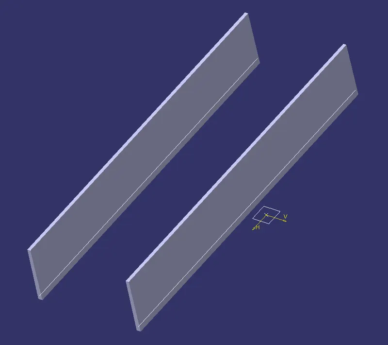
- Union trim the rib to the Door Handle Surface.
Design Procedure (Screw Bosses) -
Screw Bosses are used to provide channel for screws to attach additional components or to fix the component to another with screws. Smaller ribs are used to strengthen screw bosses.
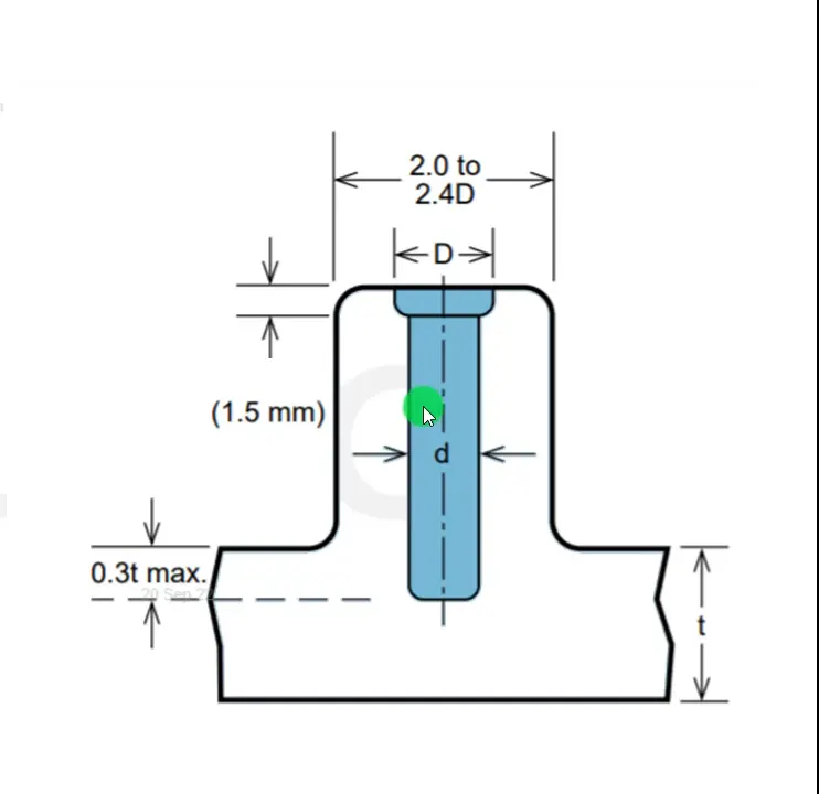
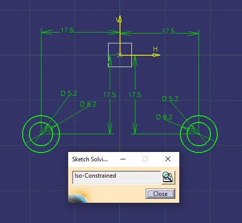
- Create an iso-constrained sketch on the surface/ plane on which the Screw Bosses will be constructed.
- Add a new Body and Pad the Sketch to get the screw boss’ profile.
- Create a sketch for smaller ribs that should support the screw bosses, pad and form the ribs with appropriate height.
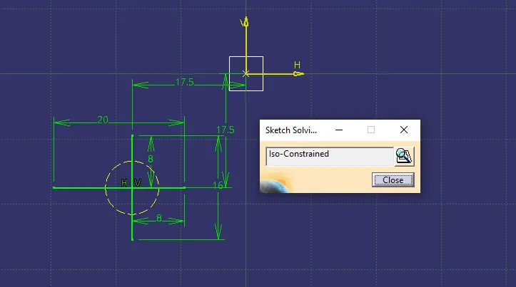
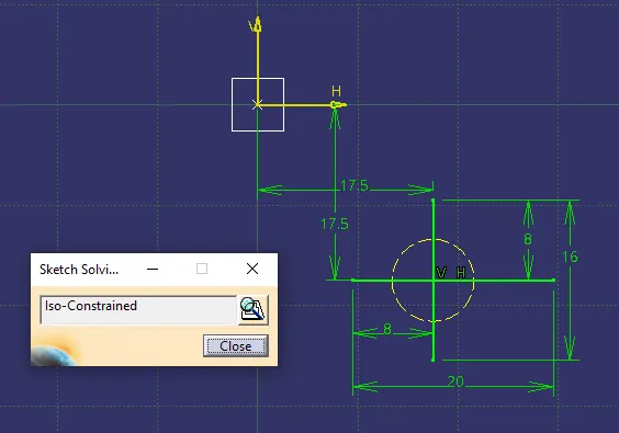
- Add a draft of 0.5deg to all the required surfaces.
- Union trim the rib to the screw boss.
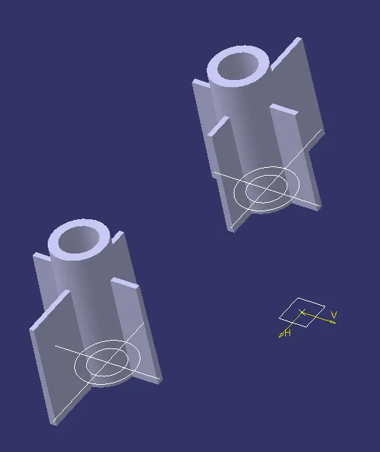
- Create the required number of screw boss components in a similar way or use the copy-paste-translate commands.
- Union trim this component to the Door Handle Surface.
Tree Structure -
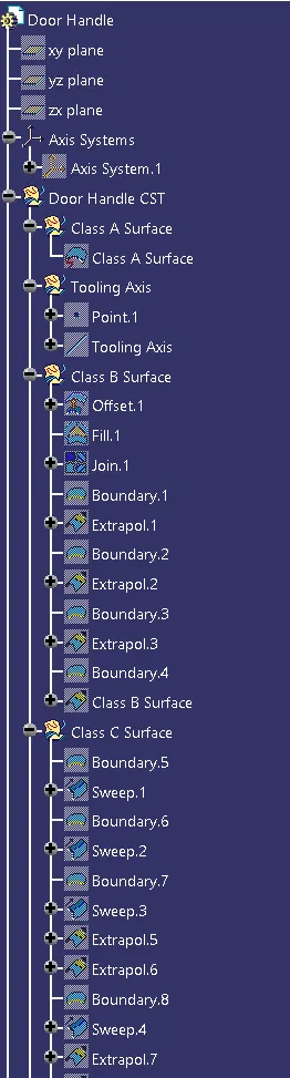
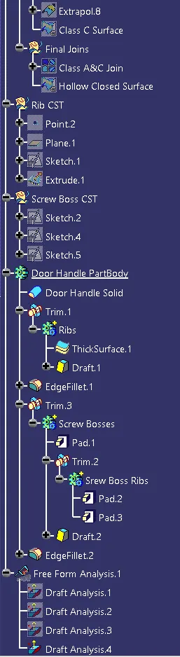
Final Part Component -
Isometric View :
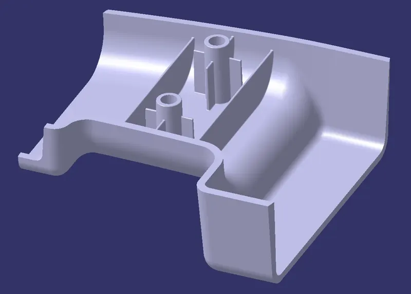
Front View :
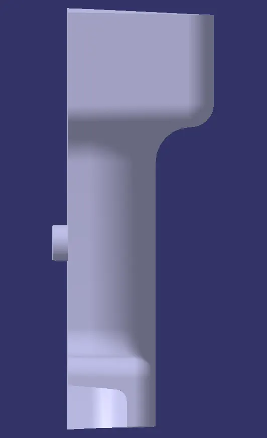
Top View :
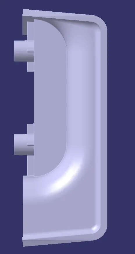
Side View :
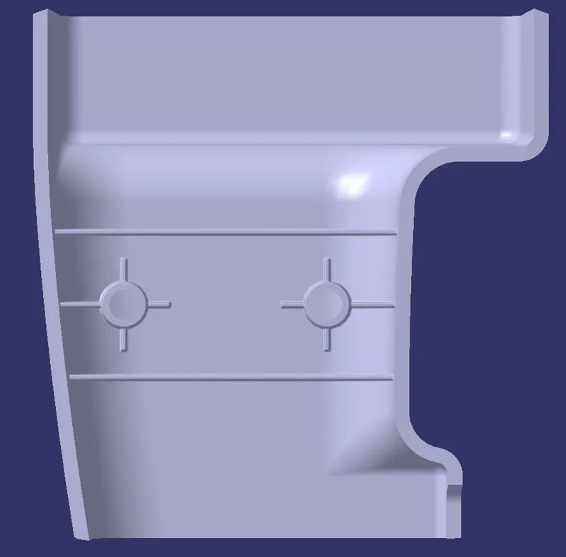
Draft Analysis -
The optimal Draft Angle is found to be 0.95deg from the given Class A Surface.
The optimal Draft Angle for attachments should be a maximum of 0.5deg.
Class A Surface :
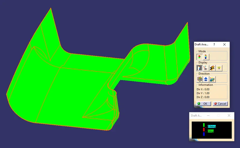
Door Handle Solid Part :
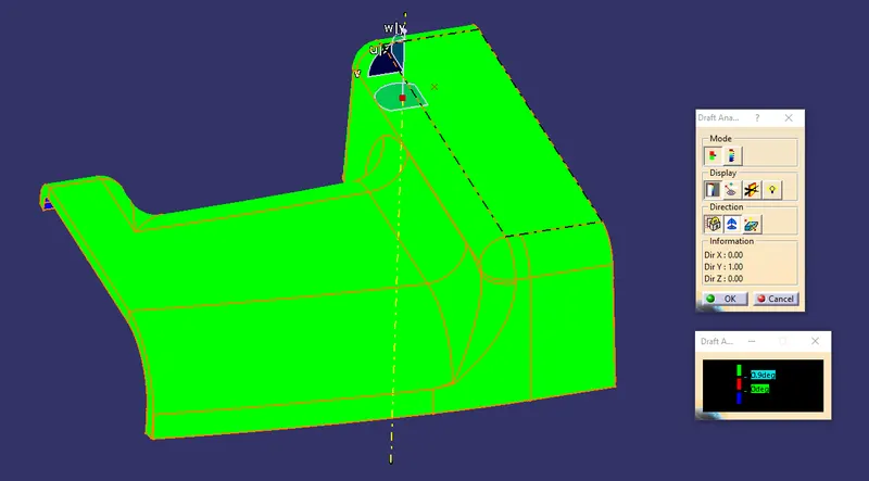
Rib Attachment :
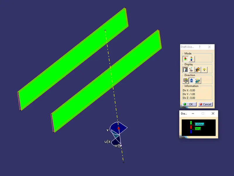
Screw Boss Attachment :
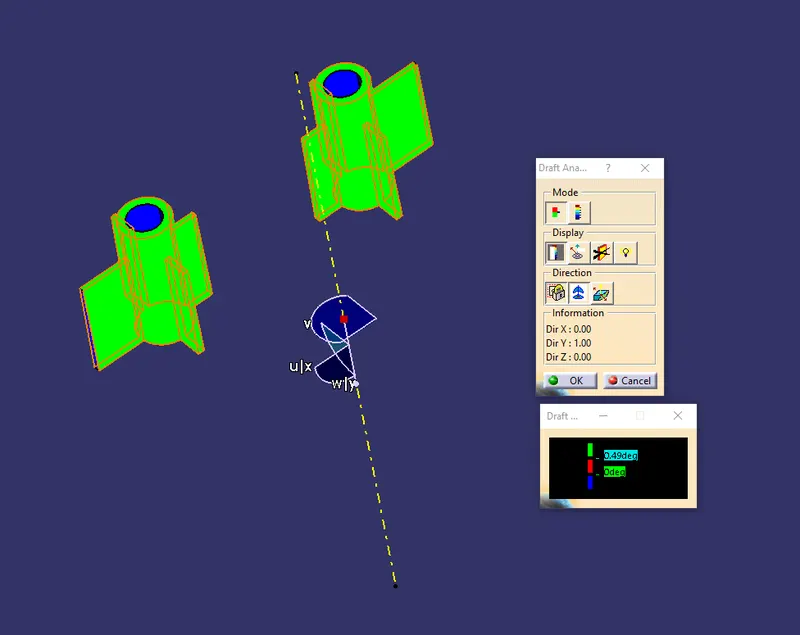
Result And Conclusion -
- The Door Handle component is designed and the Ribs & Screw Bosses are attached according to the requirements.
- Draft Analysis is done on the Class A Surface, the Solid Surface developed from the hollow closed surface, The rib attachment, the screw bosses attachment and the final Door handle part. The results all pass the inspection.