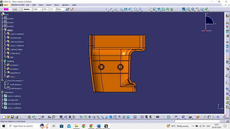
Week 10 - Challenge 1- Attachment Feature Creation (Ribs & Screw Boss)
Report:
Tool Axis Creation:
- For the tooling axis checking the all 3 axis i.e., x, y and z
- x - axis
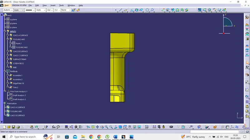
- y -axis
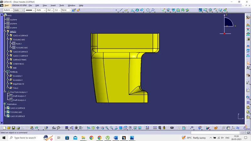
- z- axis
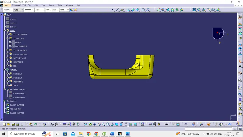
- In the above axes the y axis has better view cover major elements in the component
- By choosing y axis as reference a point is defined
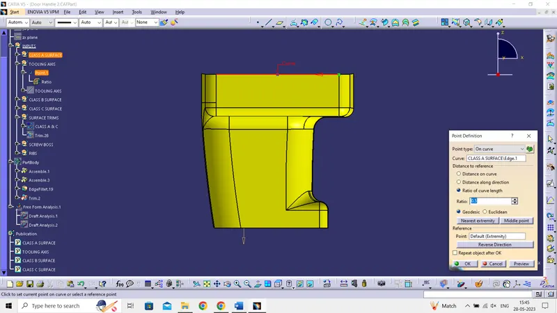
- A line is created based on the point and direction along y axis
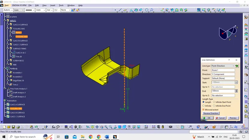
- Therefore, Tool axis is created and published
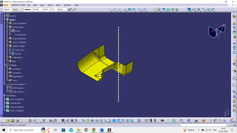
Draft Analysis:
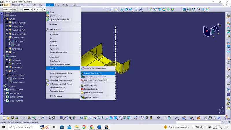
- After creating the tool axis then add the feature draft analysis in the insert section
- Change the view mode into customize view parameter then in mesh section pick material
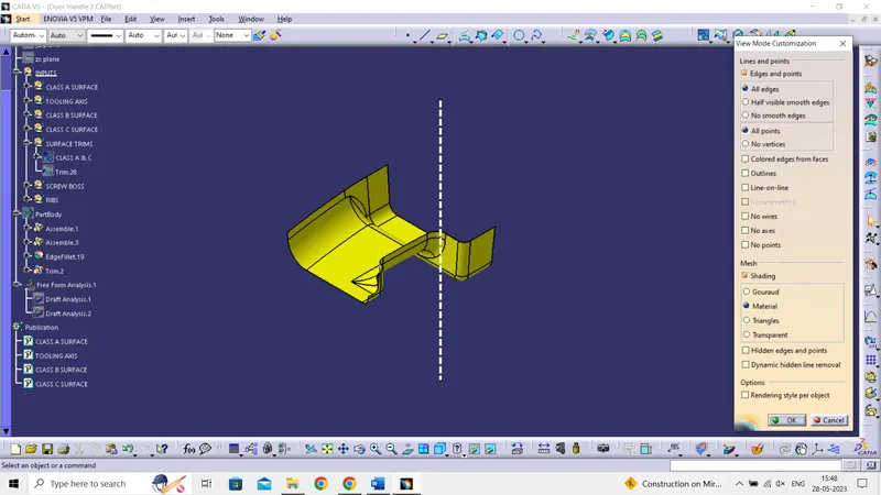
- switch to the qiuck analysis mode and display the color scale
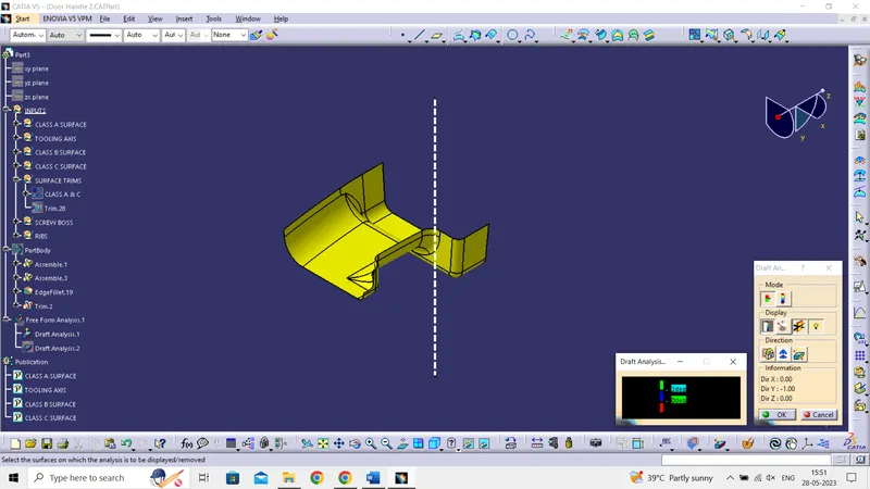
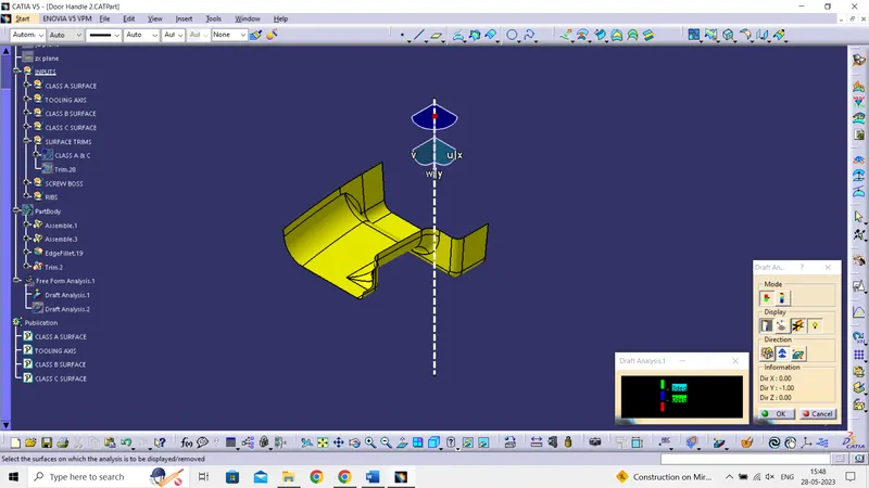
- Then in the direction section use the compass to define the draft direction by taking tool axis as reference and lock the direction
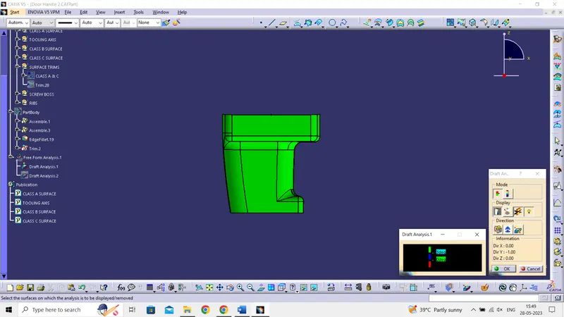
- After setting draft direction select the Class A surface which shows the draft angle i.e., 3 deg
Tree Structure and Publications: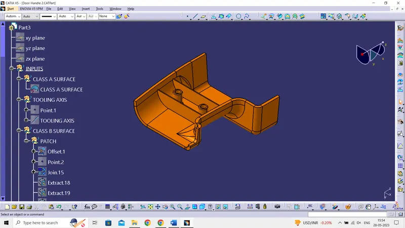
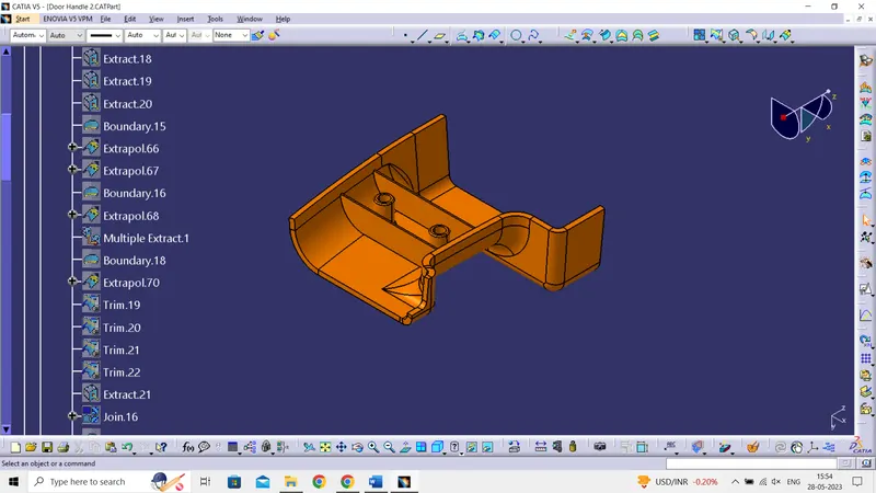
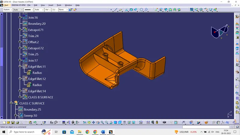
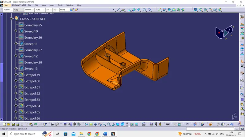
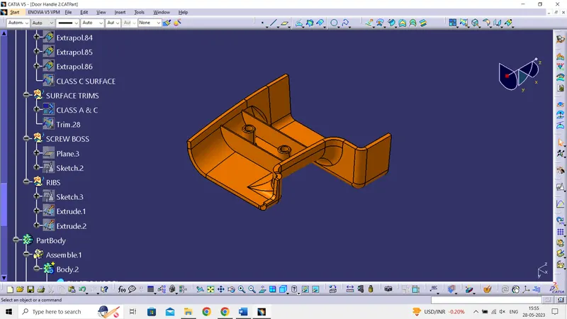
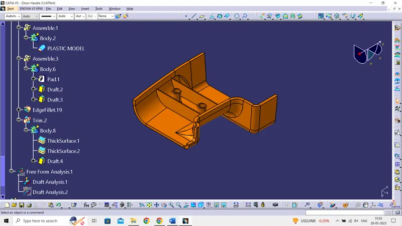
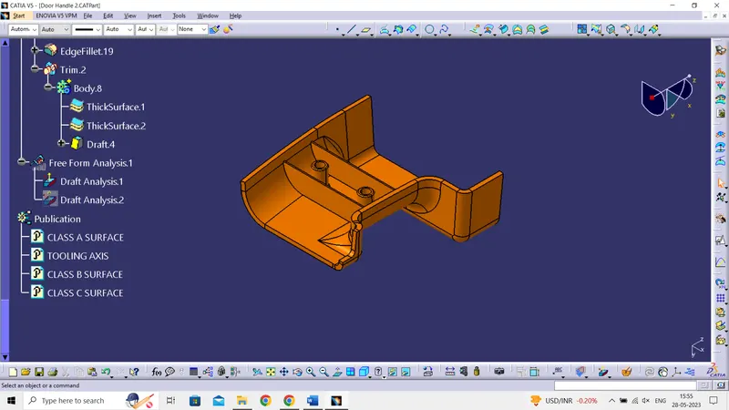
Surfaces:
- Class A Surface
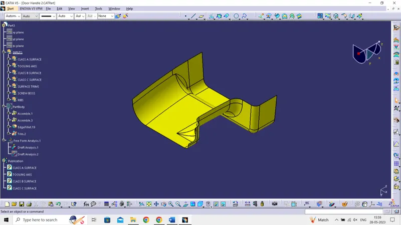
- Class B Surface
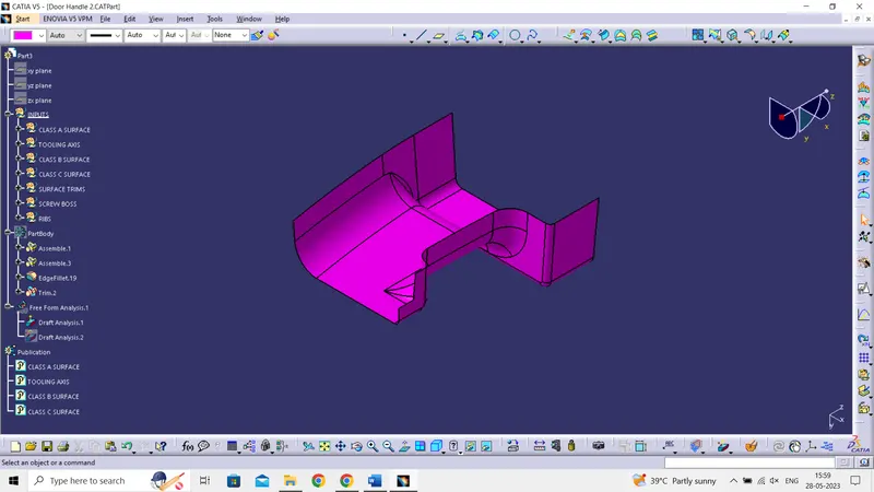
- Class C Surface
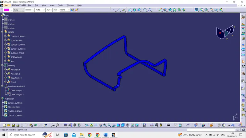
- Class A & C Join Surfaces
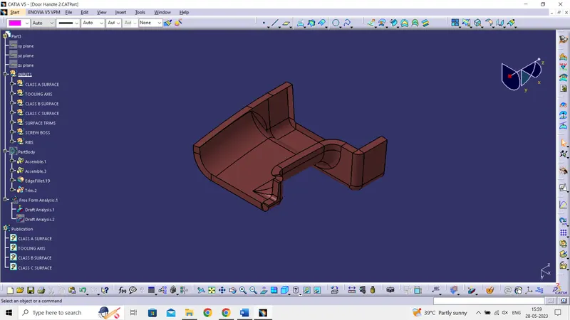
- All Class A, B and C Surfaces
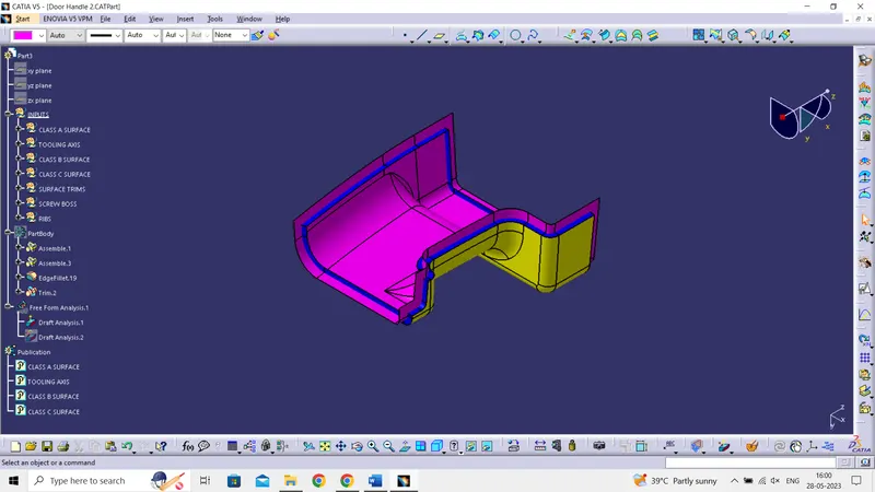
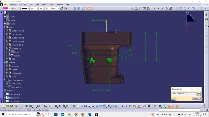
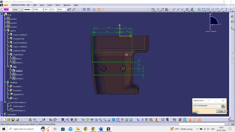
Skecth Solving Status:
- Screw Boss:
- Ribs:
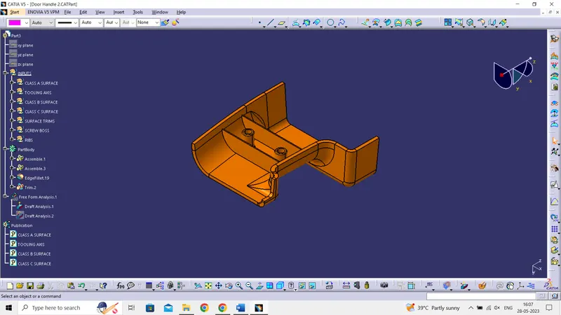
Plastic Model
- Isometric view:
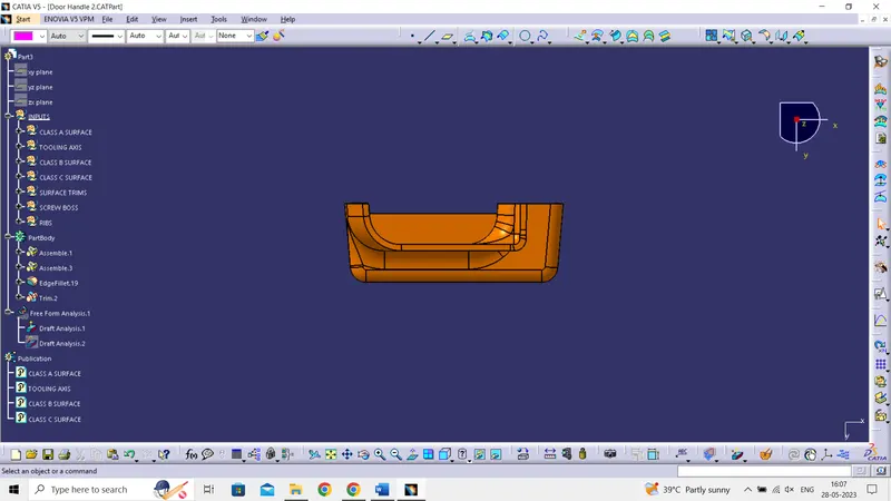
- Front View
- Side View
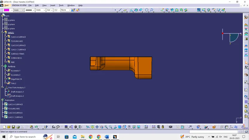
- Top View