Week 10- Assembly Workbench
In this week’s assignment, we will create 2 assemblies. we have 2D diagrams of the components and we have to first create the individual part files and then create a complete assembly of those part files in the assembly workbench.
Fristly We will create Quick Return Mechanism parts then assemble in Assembly workbench.
- Body 1:- Starting create with the positioning 2D sketch then with the help of sketch we use extrude command. this is the base of QR.
- Body 2:- For creating body 2 and 5 simply create the positioning 2D sketch then use shaft command.
- Body 3:- For body 3 we need to 2 sketch frist for shaft which is contact with body 4, ues to revolve command and second for cube which is contact with base body in which slide along the direction, ues to pad command. and then adding with the help of boolean operation.
- Body 4:- lastly create body 4 need to 2 sketch frist is base of rotation and second for handle, use to pad and shaft command.
Now we will assemble all parts in assembly workbench, which is product design. assembly design is easy to use and powerful. The basics of product structure, constraints, and moving assemblies and parts can be learned quickly. this method is most used globally and it’s very easy to be manipulated be everyone. To do an assembly in CATIA V5 it is sufficient to have the Constraints toolbar. The most used commands from this toolbars are:
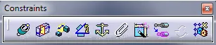
- Coincidence Constraint – this command create a coincidence constraint between two components of the active component;
- Contact constrain – creates a contact constraint between two components of the active component;
- Offset Constraint – creates an offset constraint between two components of the active component;
- Angle Constraint – creates an angular, parallelism or perpendicularity constraint between two components of the active component.
- Fix Component – Fix the component position in the active component.
Second Product is CV Joint in which 3 parts, we create to individually parts, Fristly draw positioning 2D sketch and then with the help of pad, revolve, pocke, mirror and fillet command, and applied boolen operation in which we use to add, remove and union trim for three individually body parts.
For assembling, frist we applied coincidence constraint in body 1 and 2 then add offset constraint, so it will not to move any direction but it will rotate on axis. and same coincidence constraint applied body 1 and 3, and contact constraint with body 1 and 3. this is also rotate own axis. then save file in save management.