Week 10- Assembly Workbench
DRAWING 1:
- First of all i created the every individual parts like rotor, shaft, slotter for this i created sketch according to the dimension given in the challange and than pad all the scetches to make a part body.
- For creating assambly go to CAT product and created a parant point with differnt planes and fixed them now go to command name as existing component to insert all the CAT Part one by one.
- make Publication of point , axis and x,y,z planes for all the individual CAT parts then Coincide the slot point with the parant point and fix the part and then assamble all the parts or constrained with each other according to the given in the drawing.
- after assmbling go to the MANIPULATION COMMAND UNDER MOVE tick on with respect to constraint then if we try to move the cat part in any direction it wikk not move so that we can confirm thAT our all part is fully constrained.
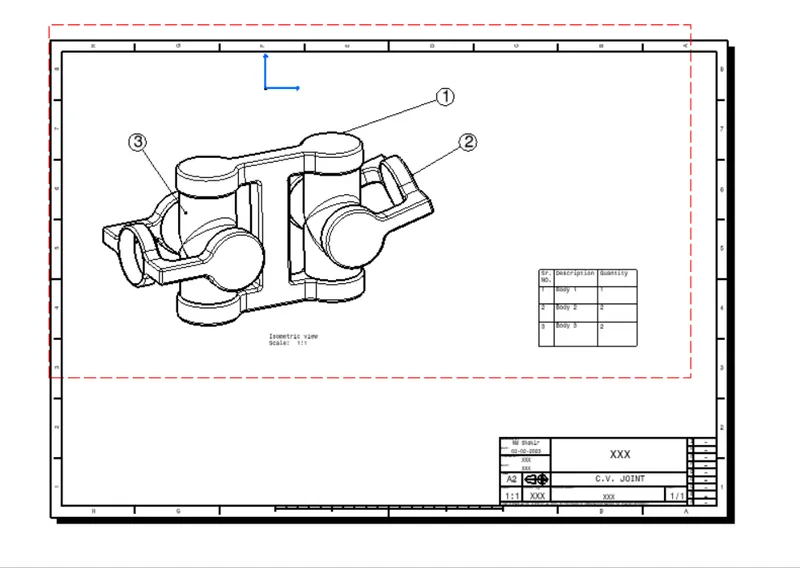
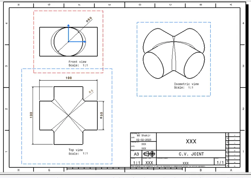
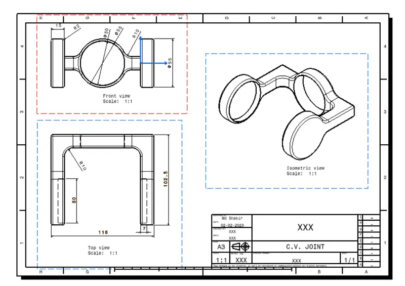
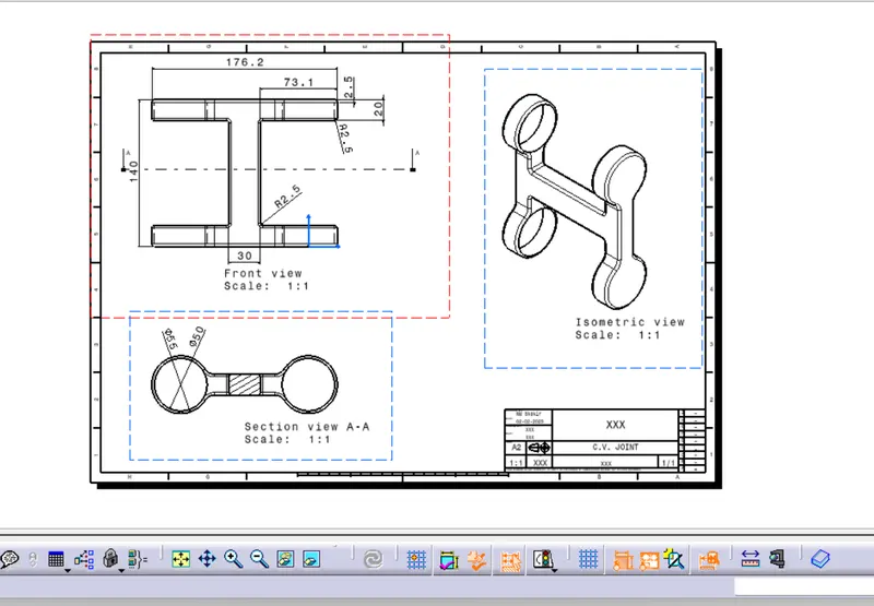
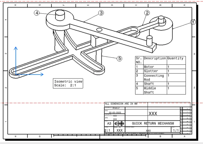
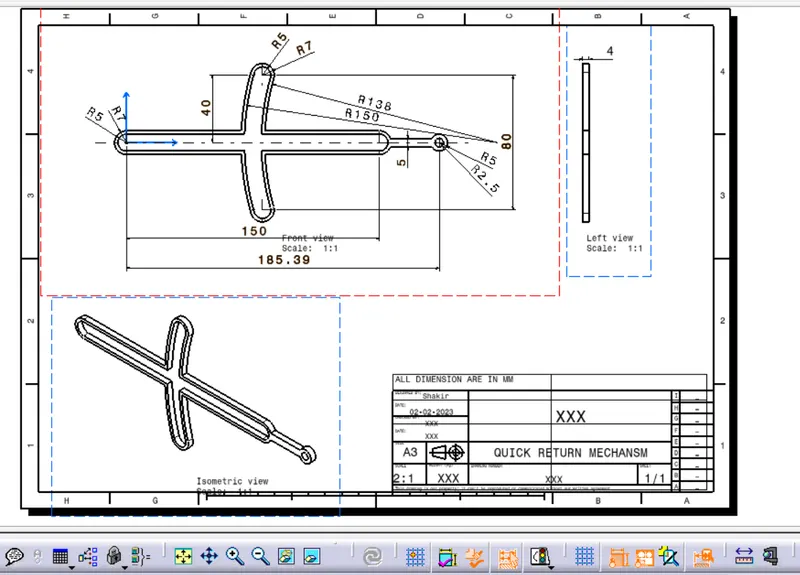
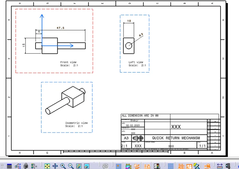
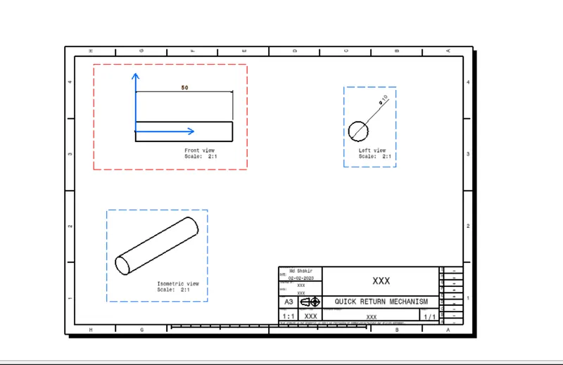
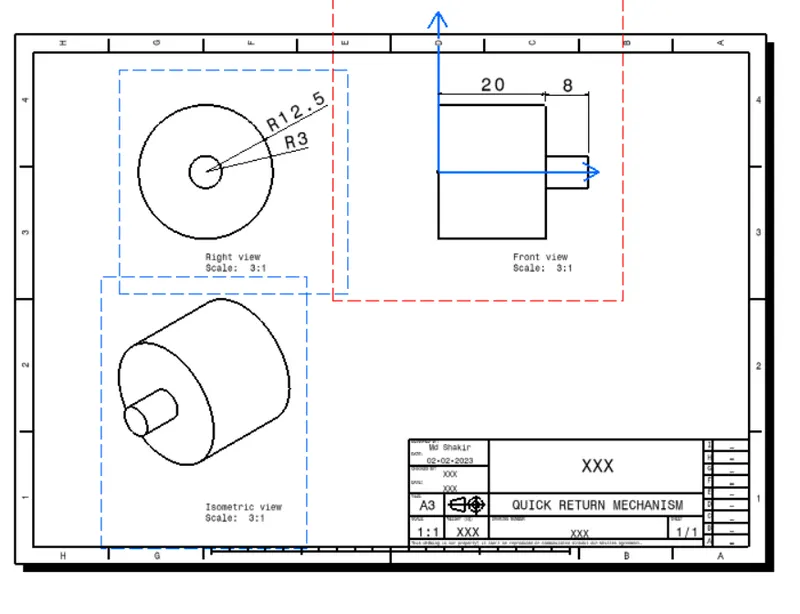
- we use Drafting tool to view all the parts in 2D as agiven below:
-
- in drafting we have created different view of the part like fromt top and side view and given the proper dimension do that it can be umderstood by the skilled operator who are gonna be manufacture it
DRAWING 2:
- First of all i created the every individual parts like rotor, shaft, slotter for this i created sketch according to the dimension given in the challange and than pad all the scetches to make a part body.
- For creating assambly go to CAT product and created a parant point with differnt planes and fixed them now go to command name as existing component to insert all the CAT Part one by one.
- make Publication of point , axis and x,y,z planes for all the individual CAT parts then Coincide the slot point with the parant point and fix the part and then assamble all the parts or constrained with each other according to the given in the drawing.
- after assmbling go to the MANIPULATION COMMAND UNDER MOVE tick on with respect to constraint then if we try to move the cat part in any direction it wikk not move so that we can confirm thAT our all part is fully constrained.
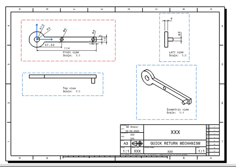
- we use Drafting tool to view all the parts in 2D as agiven below:
- in drafting we have created different view of the part like fromt top and side view and given the proper dimension do that it can be umderstood by the skilled operator who are gonna be manufacture it