Week 10- Assembly Workbench
AIM
create 2 assemblies according to the 2D diagrams of the components . create the individual part files and then create a complete assembly of those part files in the assembly workbench.
QUICK RETURN MECHANISM
A quick return mechanism is an apparatus to produce a reciprocating motion in which the time taken for travel in return stroke is less than in the forward stroke. It is driven by a circular motion source (typically a motor of some sort) and uses a system of links with three turning pairs and a sliding pair. A quick-return mechanism is a subclass of a slider-crank linkage, with an offset crank.
First create the individual parts of qucik return mechanism by following the 2D diagrams
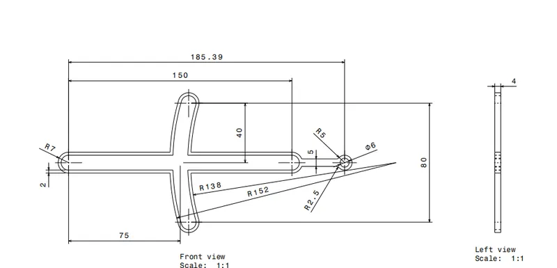
Fig.1. 2D drawing of component 1
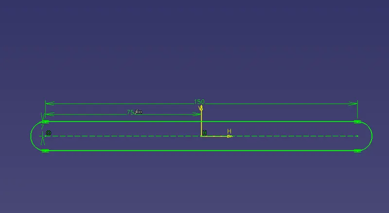
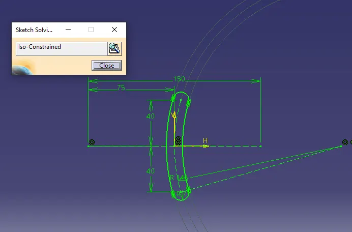
Fig.2. sketch for the component
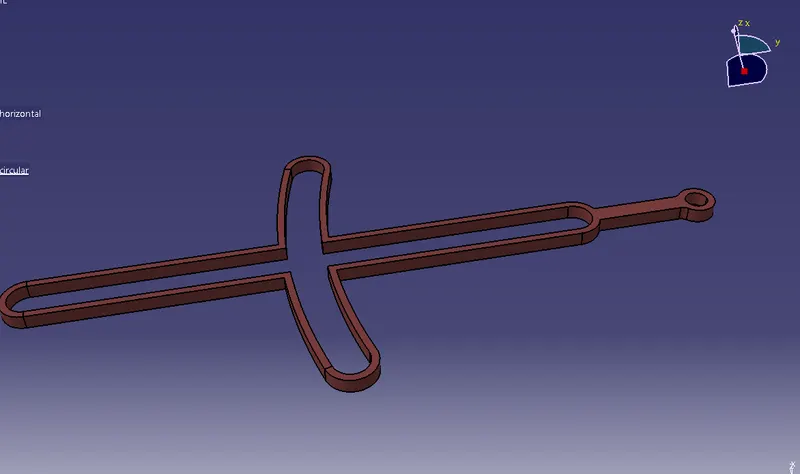
fig.3. Component 1 (slotted frame )
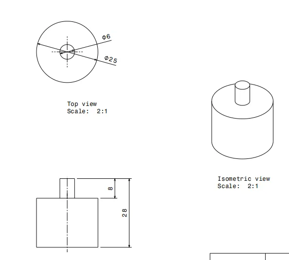
Fig.4. 2D drawing of component 2
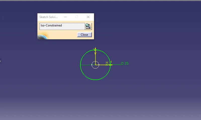
Fig.5.sketch for component 2
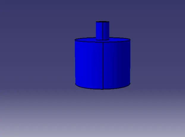
fig.6. component 2(circular block )
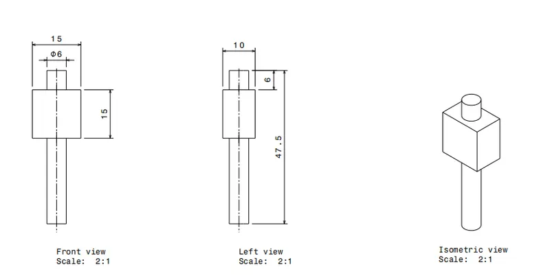
Fig.7. 2D drawing of component 3
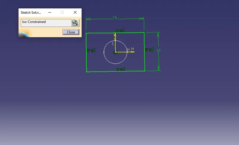
Fig.8.sketch for component 3
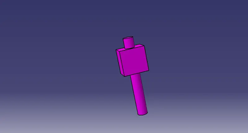
Fig.8. component 3(sliding block )
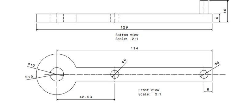
Fig.9. 2D drawing of component 4
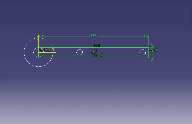
Fig.10.sketch for component 4
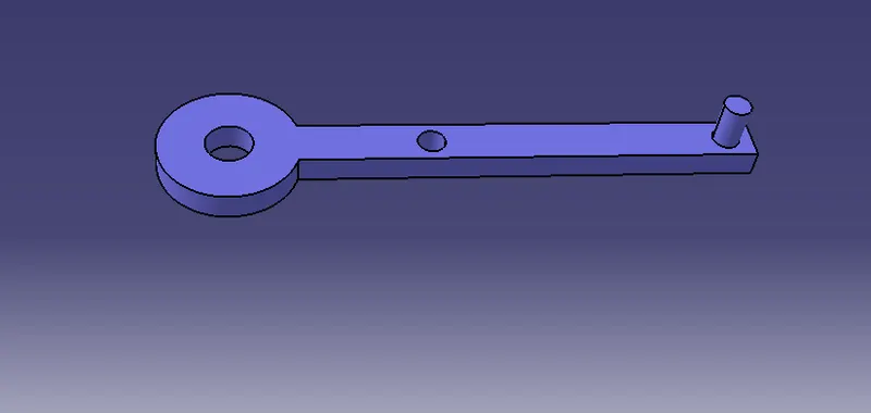
Fig.11. component 4( crank )
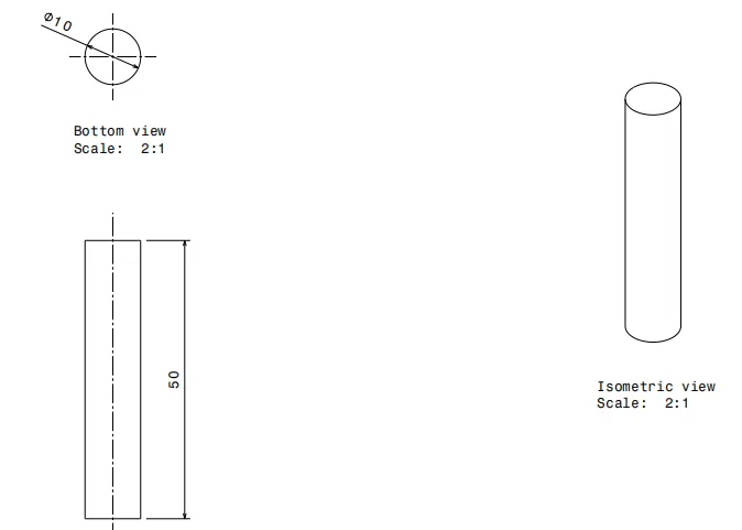
Fig.12. 2D drawing of component 5
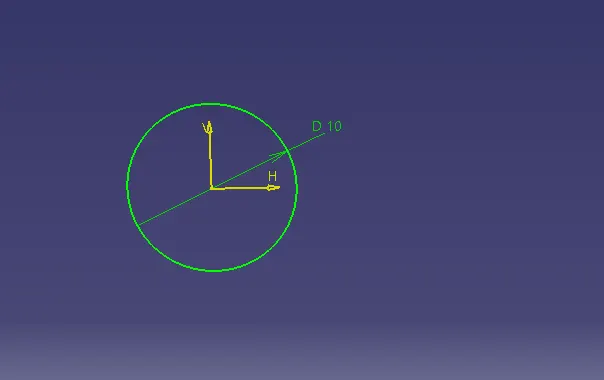
Fig.13.sketch for component 5
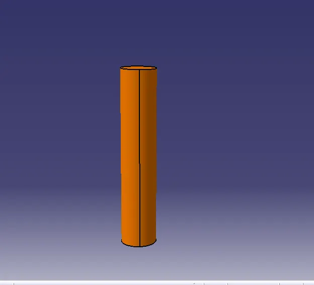
Fig.14. component 5( sliding pin)
All the parts of quick return mechanism created and open the product work bench to create the assembly.
proper constraints provided for the quick return mechanism and finally check the constraints by using the explore tool 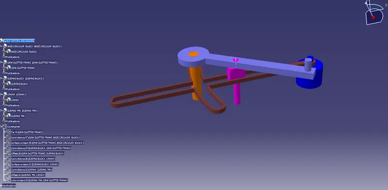
Fig.15. quick return mechanism constraints
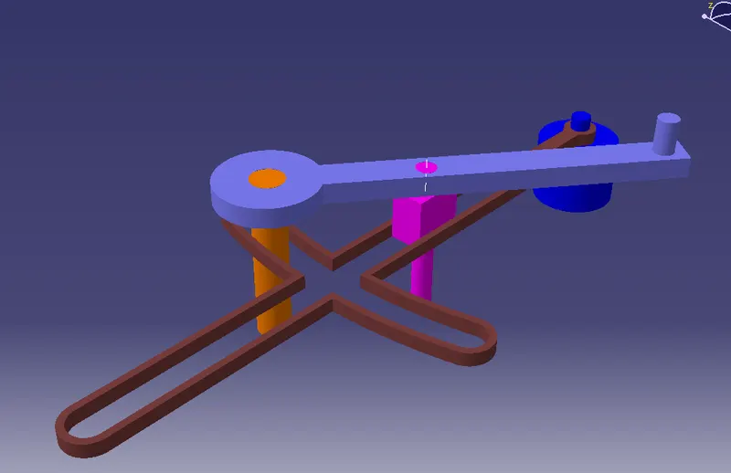
Fig.16 .quick return mechanism assembly
C V JOINT
Constant-velocity joints (also known as homokinetic or CV joints) allow a drive shaft to transmit power through a variable angle, at constant rotational speed, without an appreciable increase in friction or play. They are mainly used in front-wheel drive vehicles.
First create the parts of C V joint by using the 2D drawing
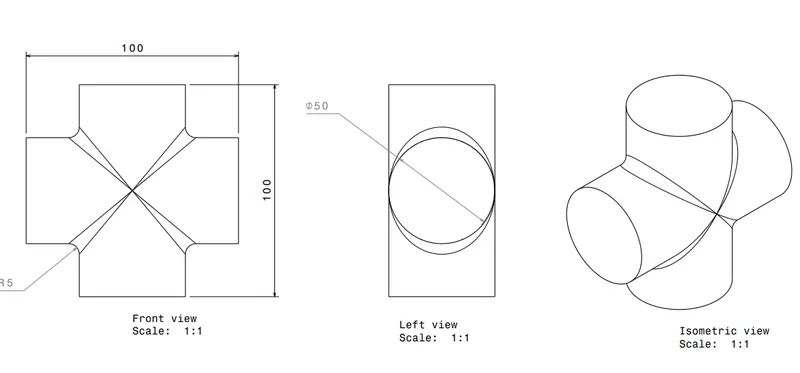
fig.17. 2D drawing of component 1
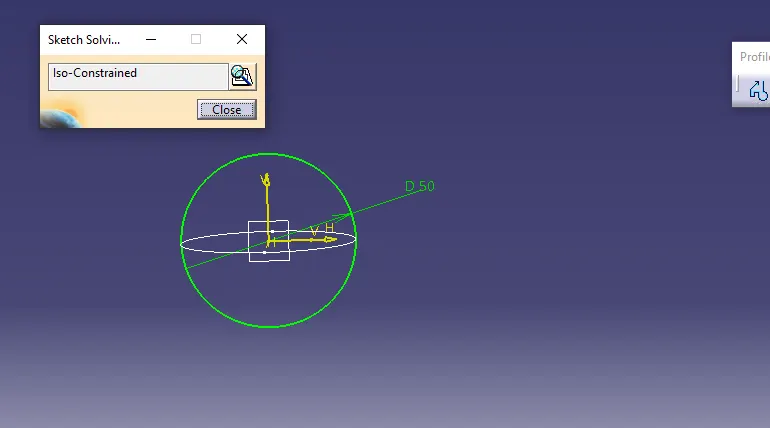
Fig.18.sketch for component 1
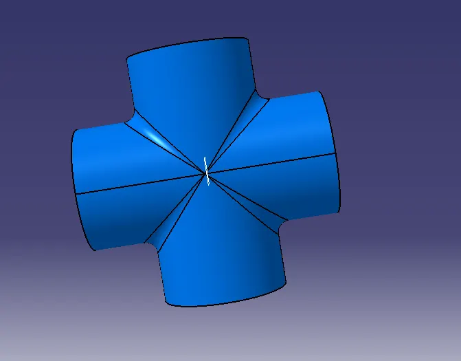
fig.19. component 1
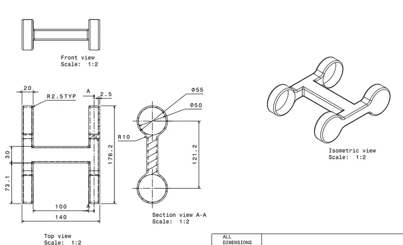
fig.20. 2D drawing of component 2
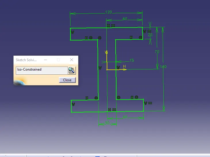
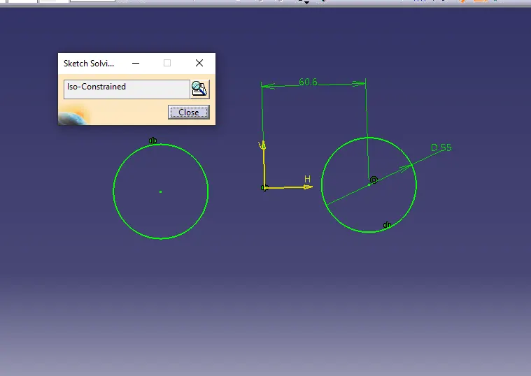
Fig.21.sketch for component 2
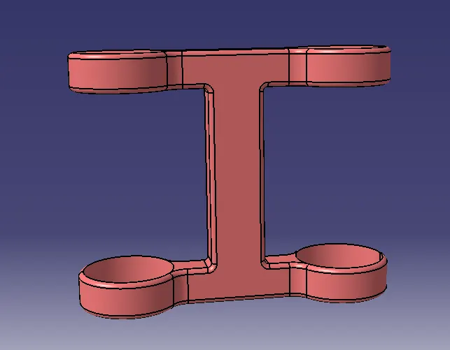
Fig.22.component 2
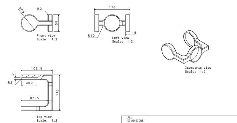
fig.23. 2D drawing of component 3
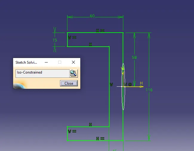
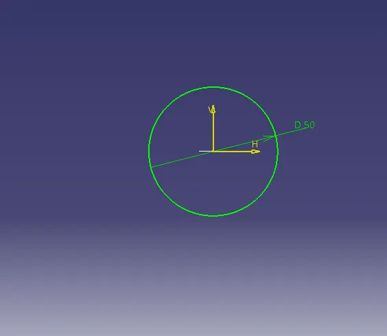
Fig.24.sketch for component 3
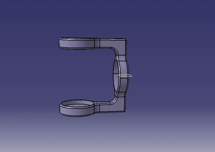
Fig.25.component 3
All the parts of C V joint created and open the product work bench to create the assembly.
proper constraints provided for the C V joint and finally check the constraints by using the explore tool.then use update, all the parts return to constaints position .
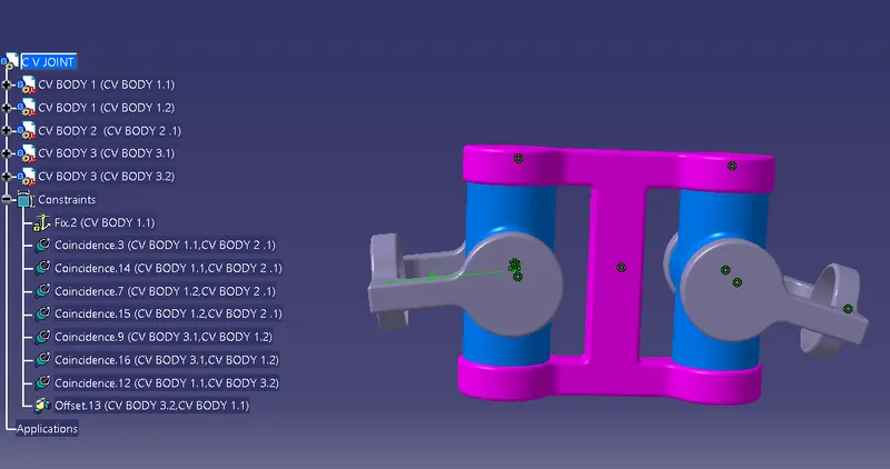
Fig.26. C V joint constraints
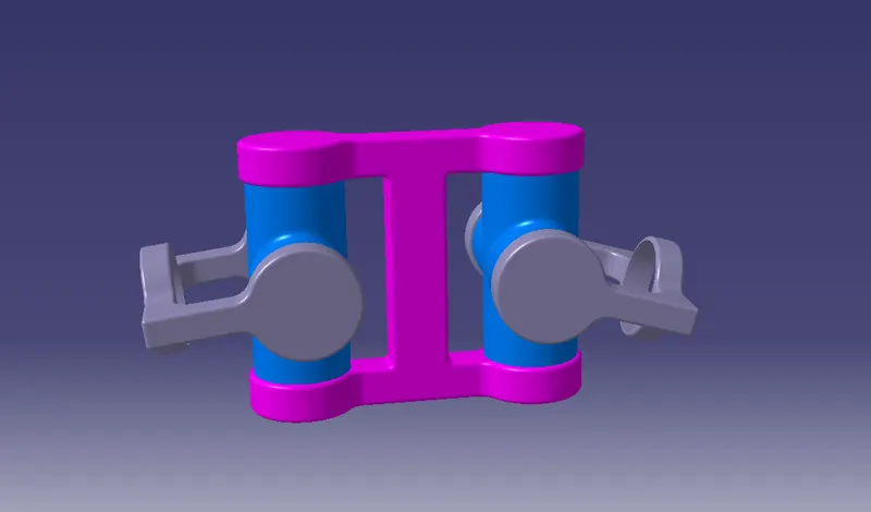
Fig.27. C V joint Assembly
CONCLUSION
Individual parts for the C V joint and qucik return mechanism created by using the 2D diagrams of component .Successfully assemble the C V joint and quick return mechanism by providing the proper constraints .