Week 10- Assembly Workbench
Introduction about Assembly :-
Assembly modelling is the process of creating designs that consist of two or more components assembled together at their respective work positions, the component are brought together and assembled in assembly design workbench by applying suitable parametric assembly constraints to them.
Component parts and subassemblies are defined as the process moves up towards the top-level assembly with this approach as the design of a key component is completed, its geometry may or may not be used to aid the design of related mating component.
Assembly of quick return mechanism:
- A Quick return mechanism is an appartus to produce a reciprocating motion in which, the time taken for return stroke is less than the forward stroke .
- It is driven by a circular motion source and uses a system of link with three turning pairs and a sliding pair.
- A quick return mechanism is a subclass of a slider crank linkage, with an offset crank.
Assembly of quick return mechanism:
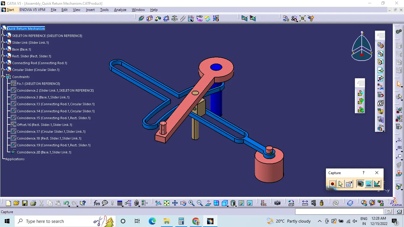
After all the parts are created, the parts are opened in new product file. The parts will come inside the product file as seperate parts which we can edit also.

First the base part or the initial part is fixed. The using coinsidence constrains and contact constrains and offset constrains the parts are assembled.
Coinsidence constrains will assemble the body with respective part axis or point - axis.
Contact constrain will asseble the faces that we selected in order to assemble.
Offset constrain will create a distance when we feel like two parts are intersecting.
Then the assembled parts are checked whether the parts will move or not using manipulation. Manipulation will help to move the parts in respective direction and direction of rotation.
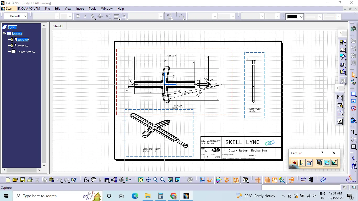
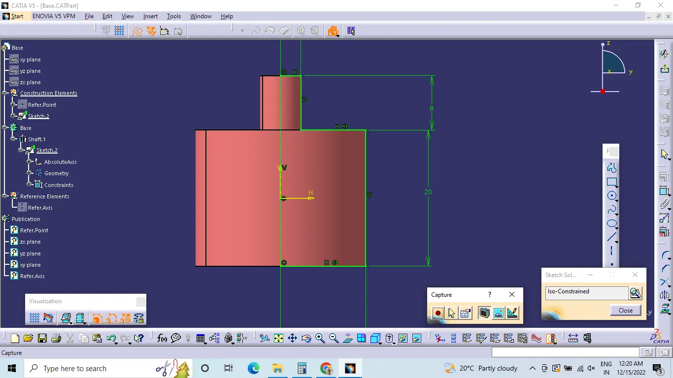
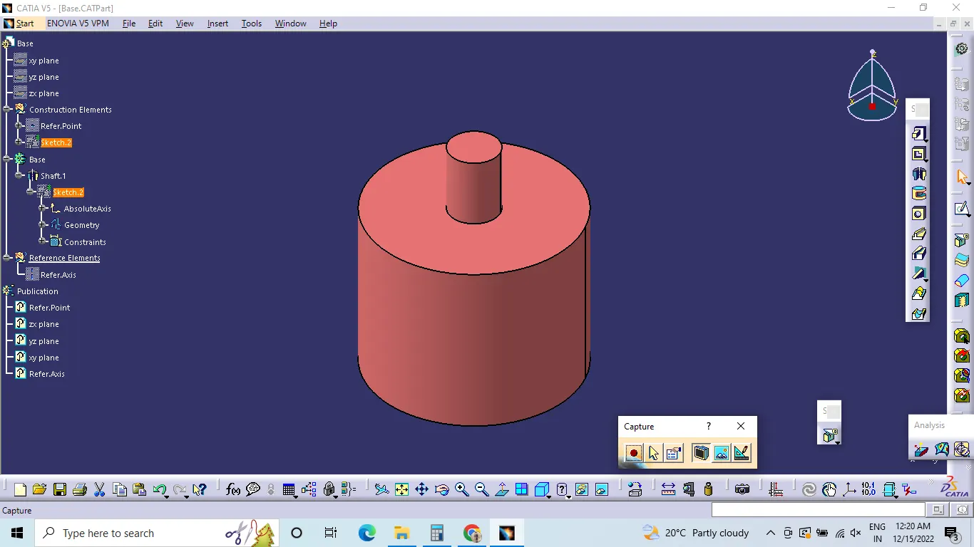
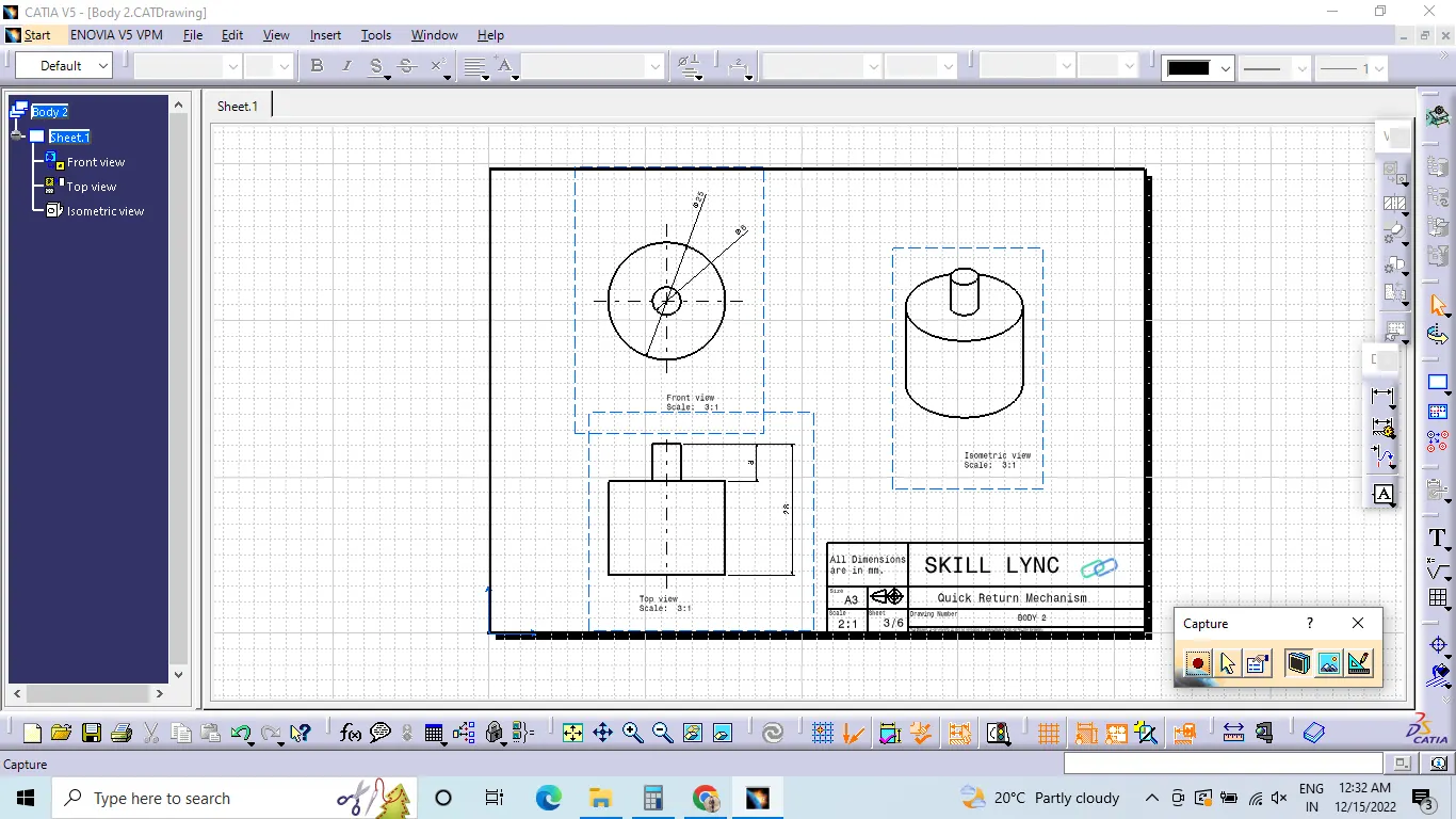
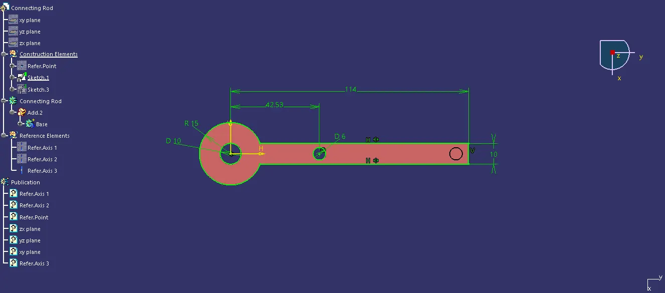
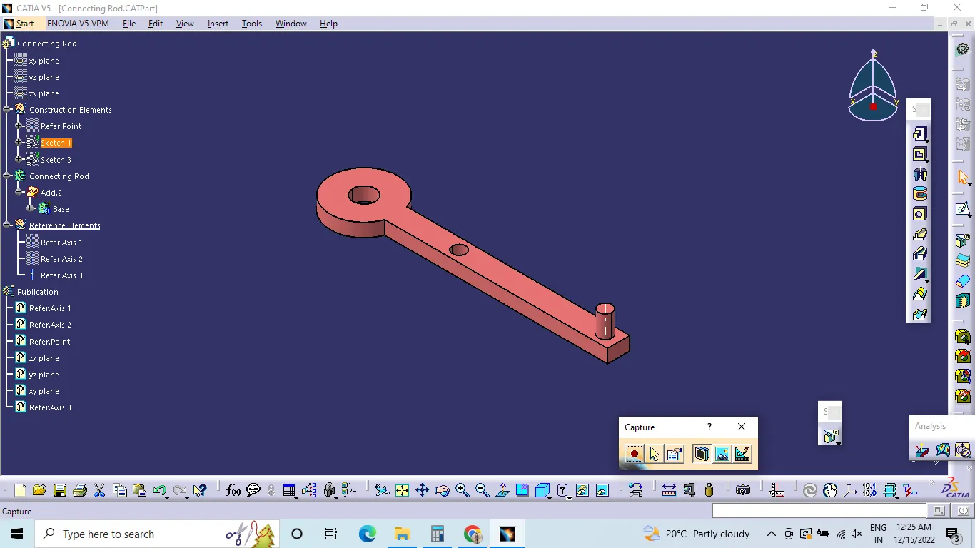
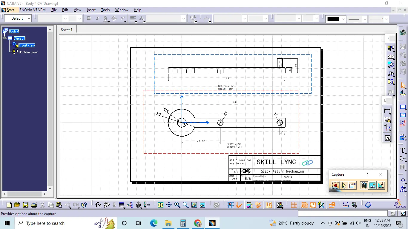
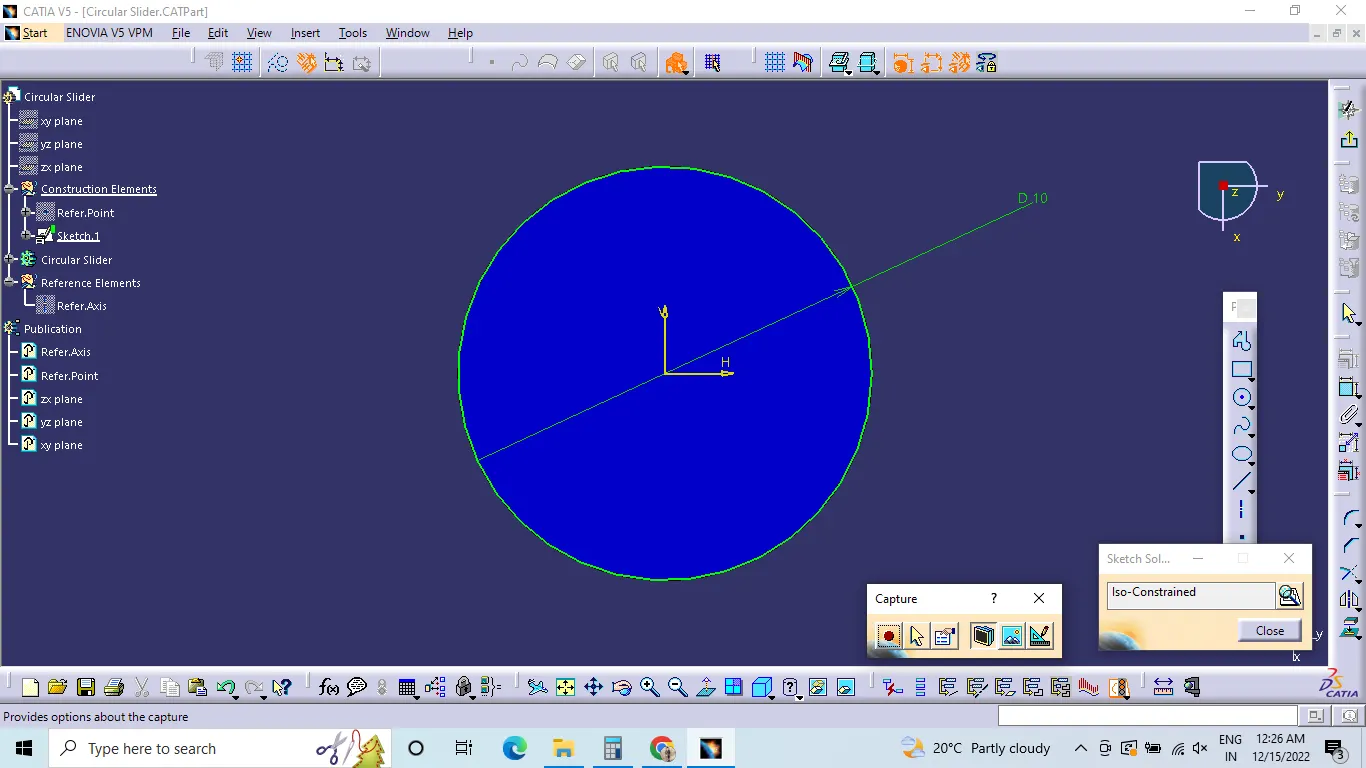
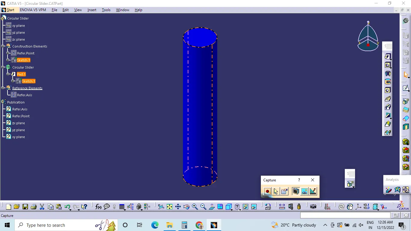
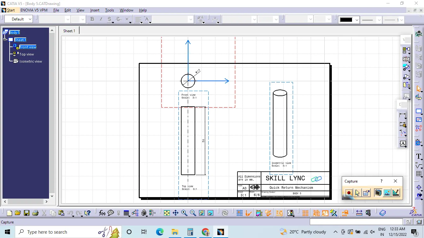
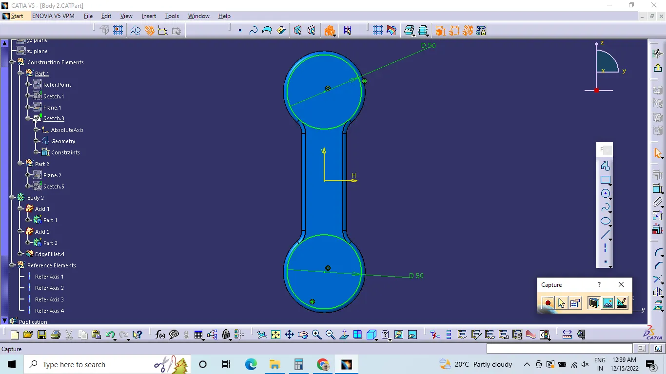
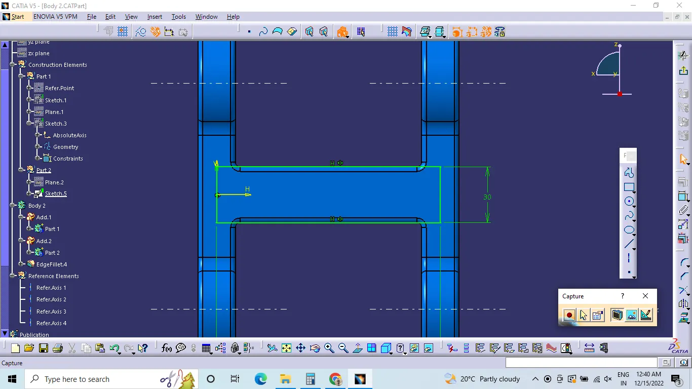
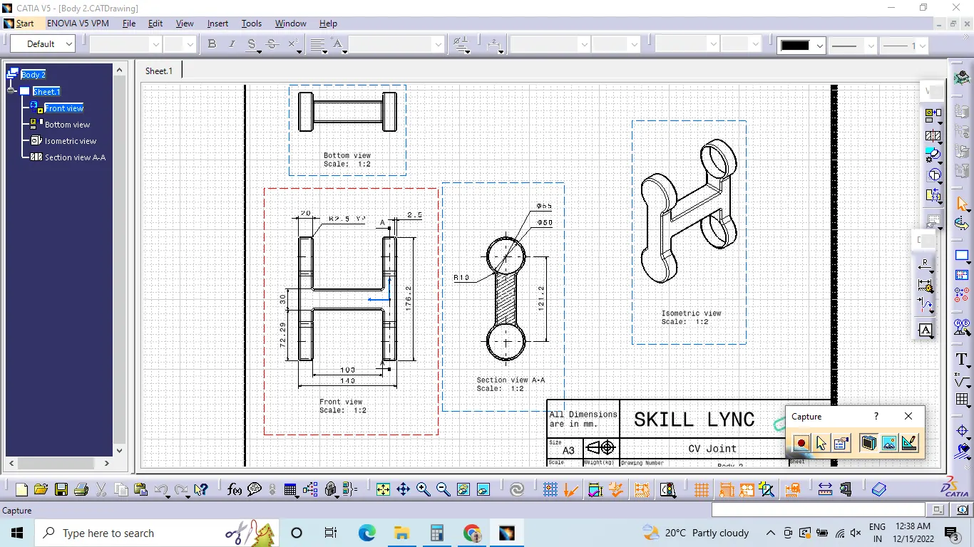
Below are the reference images showing Part Sketch, Tree structure, Part body and 2D Drafting,
Body 1 :-
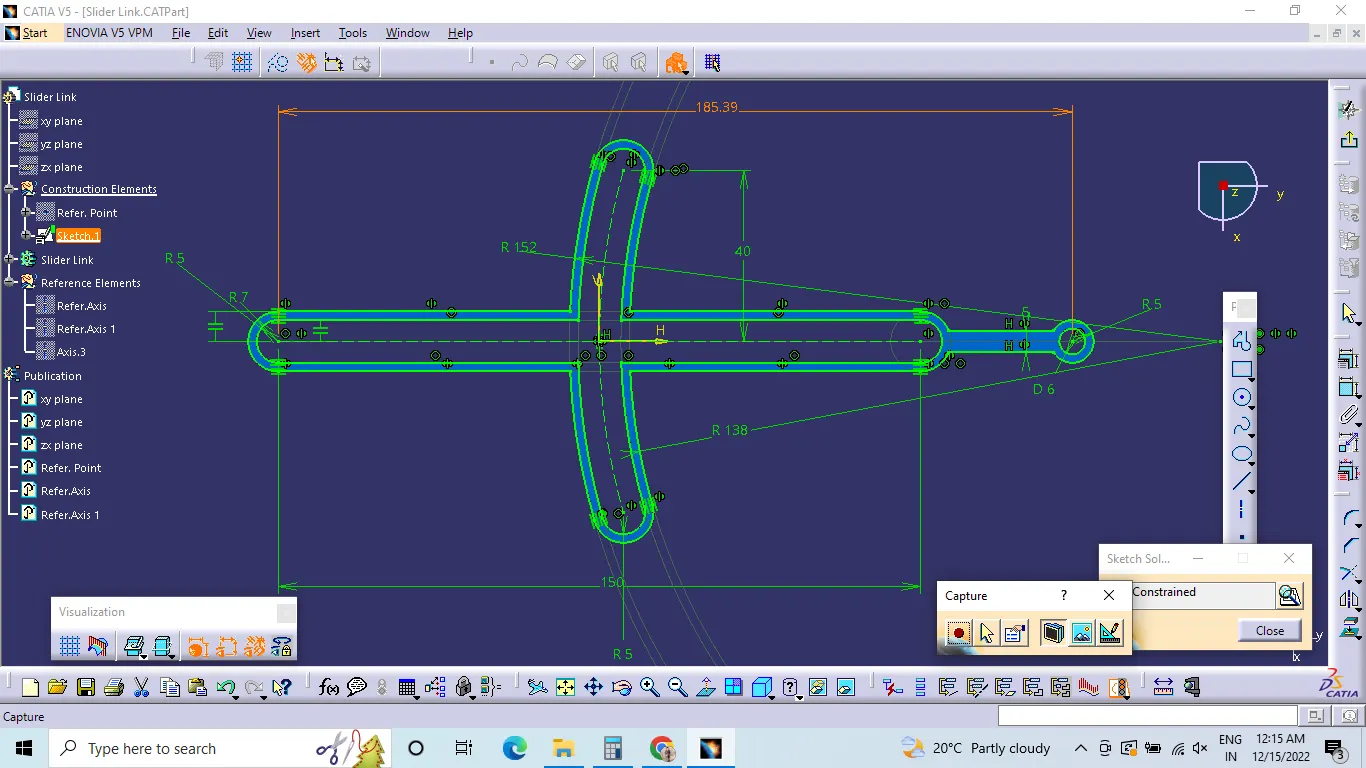
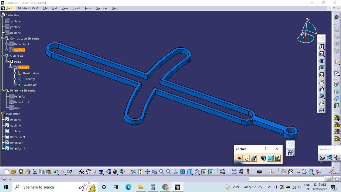
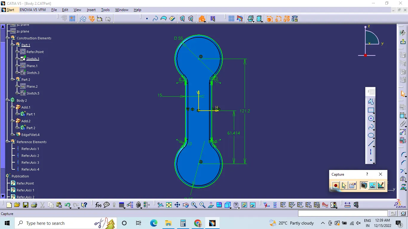
Body 2:-
Body 3 :-
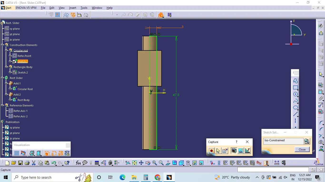
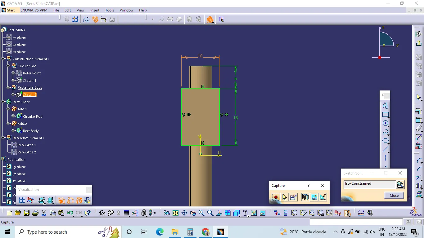
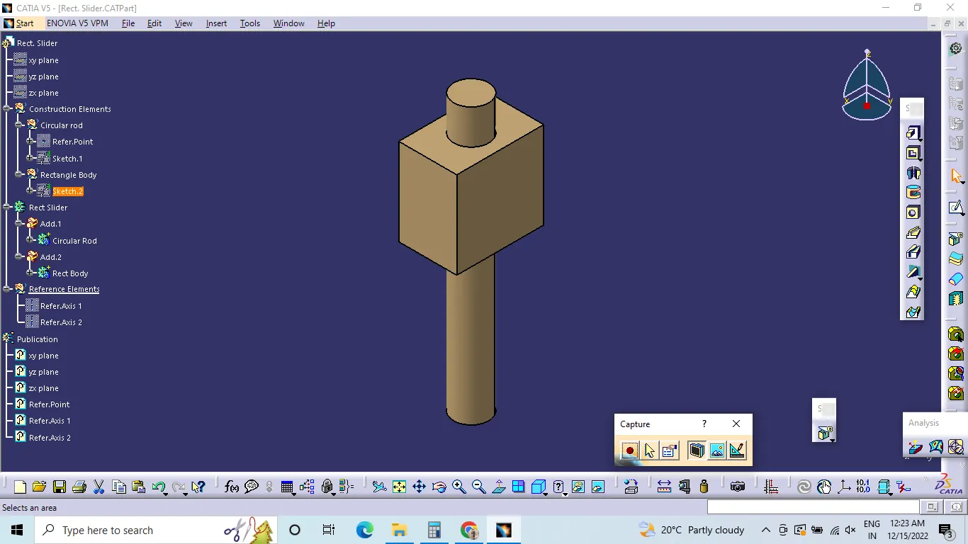
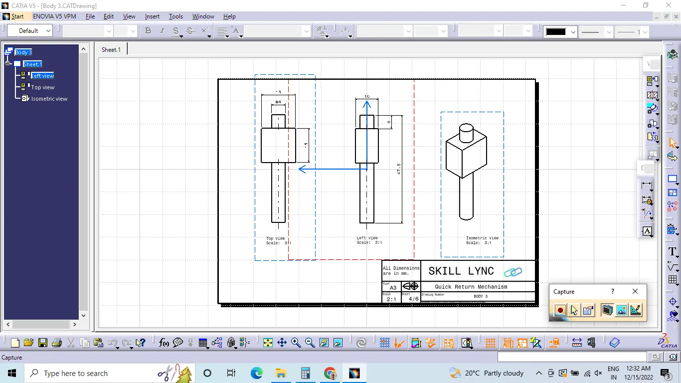
Body 4 :-
Body 5 :-
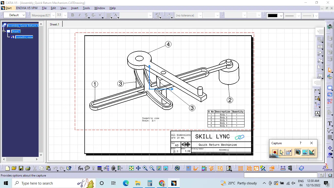
Assembly : -
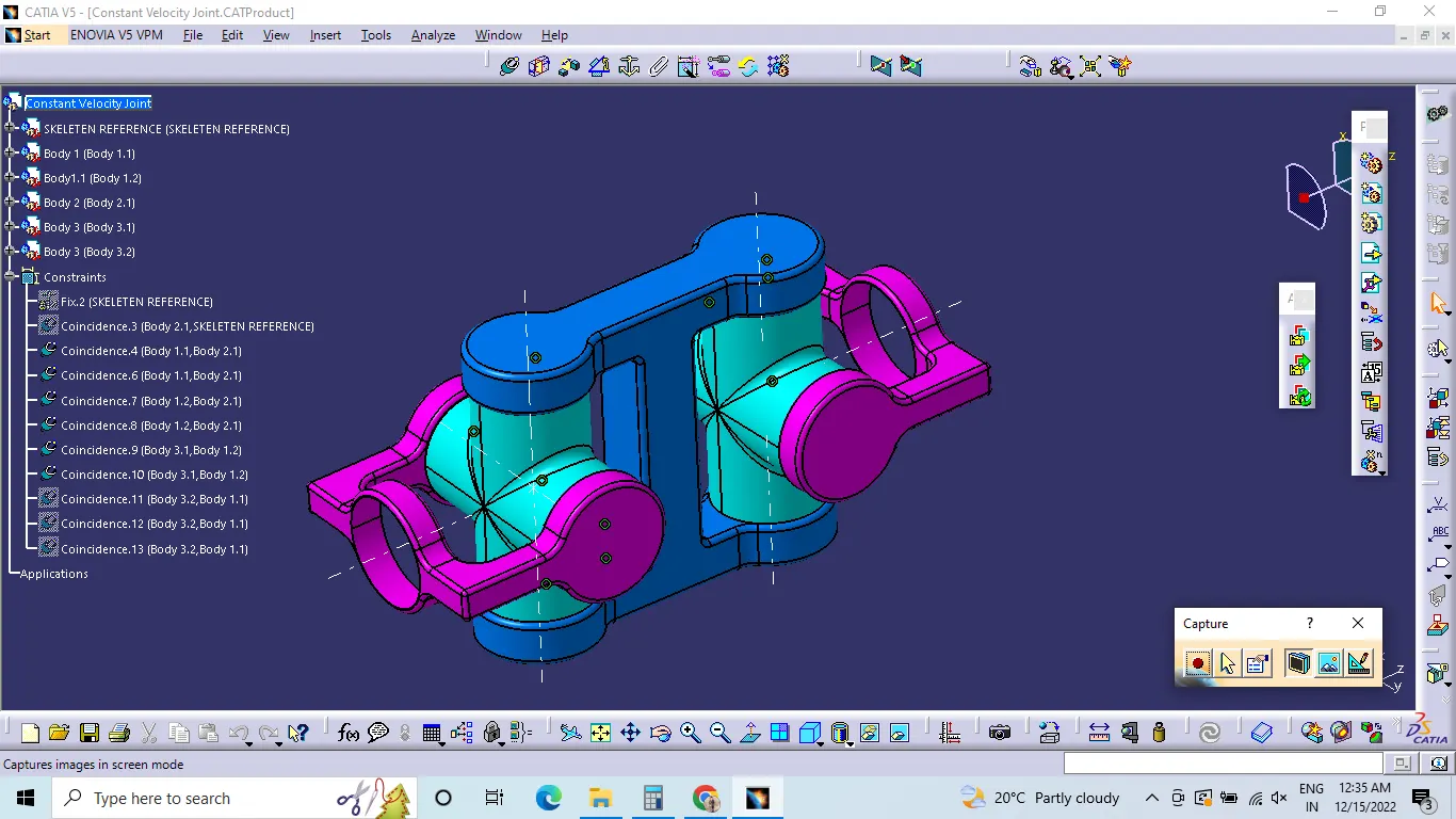
2) CV Joint:
Constant Velocity joint better known as CV Joints are found at the ends of driven shafts. They are essential to connecting the drive shafts to the transmission and wheels because of their function and location, these joints easily wear out over time to ensure that you understand the important of them.
After all the parts are created, the parts are opened in new product file. The parts will come inside the product file as seperate parts which we can edit also.
First the base part or the initial part is fixed. The using coinsidence constrains and contact constrains and offset constrains the parts are assembled.
Coinsidence constrains will assemble the body with respective part axis or point - axis.
Contact constrain will asseble the faces that we selected in order to assemble.
Offset constrain will create a distance when we feel like two parts are intersecting.
Then the assembled parts are checked whether the parts will move or not using manipulation. Manipulation will help to move the parts in respective direction and direction of rotation.
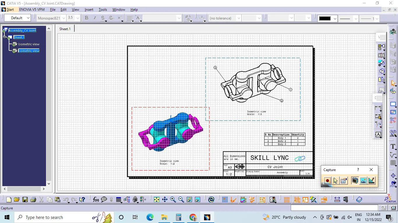
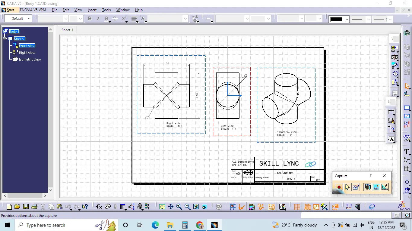
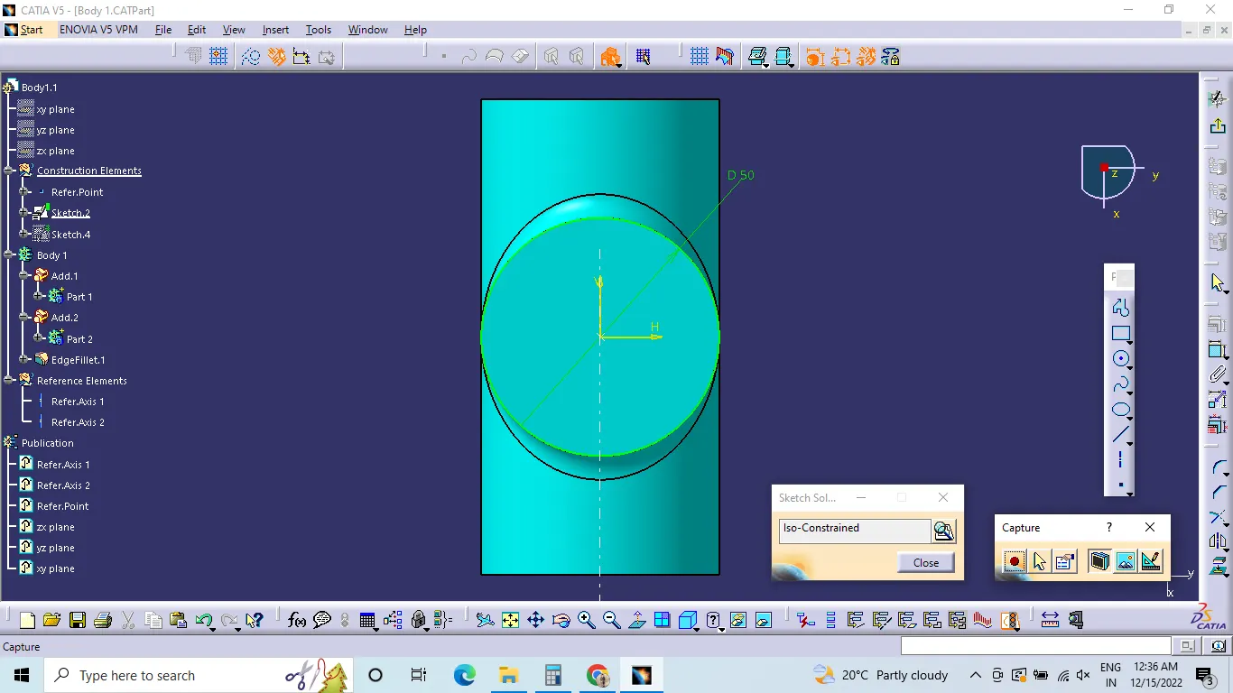
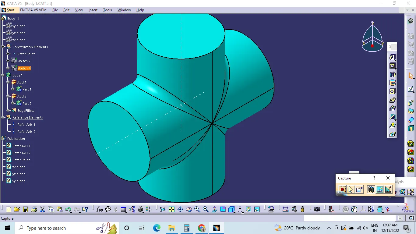
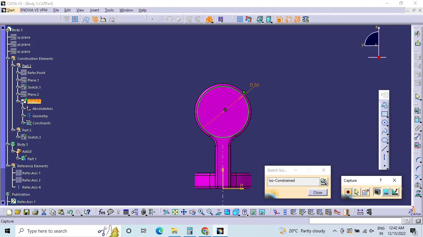
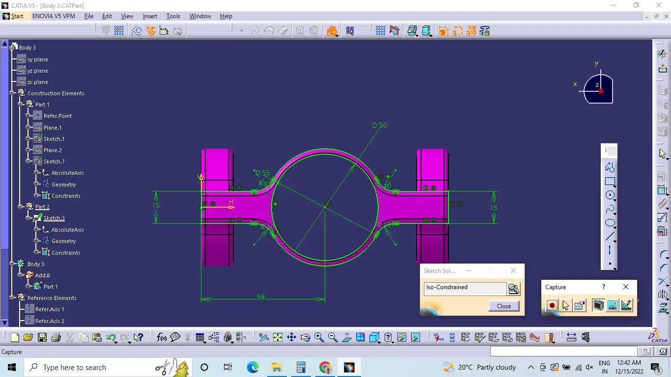
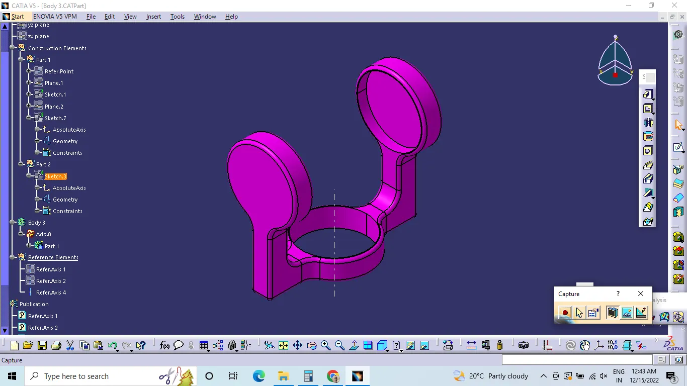
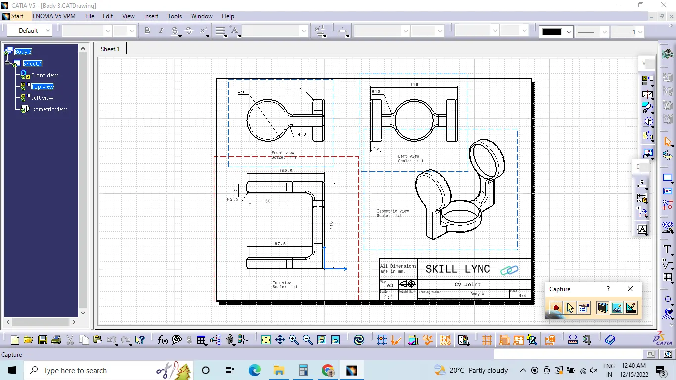
Below are the reference images showing Part Sketch, Tree structure, Part body and 2D Drafting,
Body 1 :-
Body 2 :-
Body 3 :-
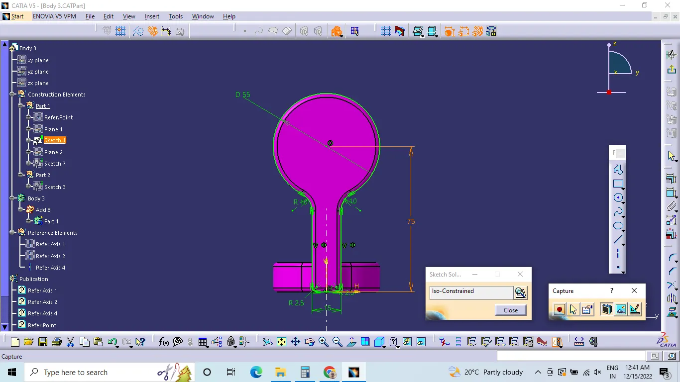
Assembly :-