Week 10- Assembly Workbench
ASSEMBLY WORKBENCH
AIM: To create assemblies for the given model drawings in the assembly workbench and to make use of the drafting tools to create 2D drawings of the individual part bodies and their assemblies.
(A) ASSEMBLY 1 (QUICK RETURN MECHANISM):
The given 2D diagrams of the components of Quick Return Mechanism consists of 5 different part bodies. These parts are modelled individually in part design and are later assembeled in the assembly workbench to form the Quick Return Mechanism.
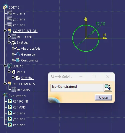
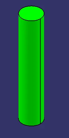
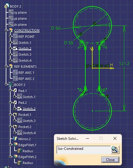
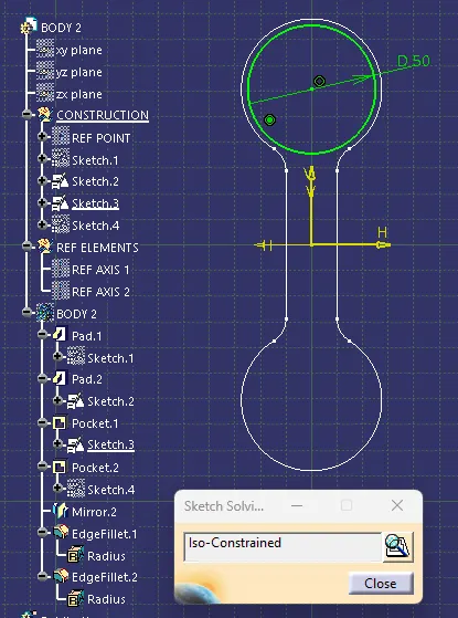
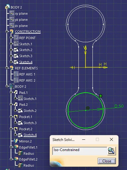
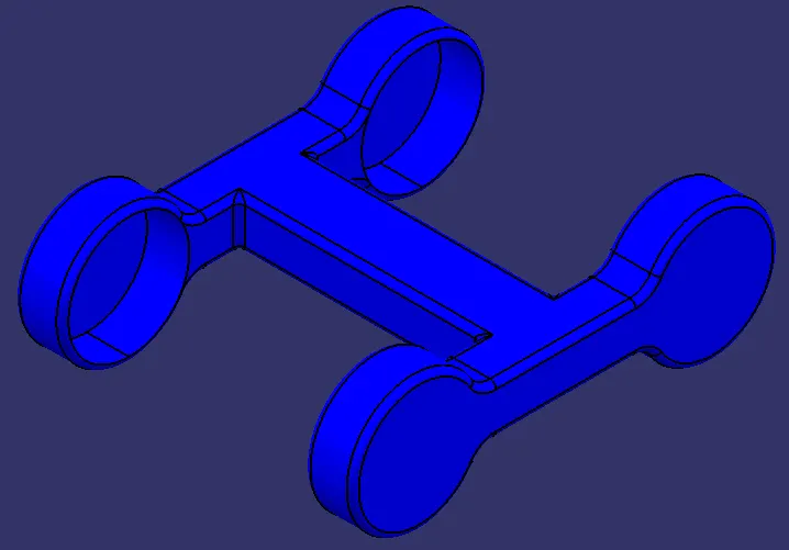
The 3D models along with the 2D sketches and the sketch solving statuses of the parts are shown below:
BODY 1:
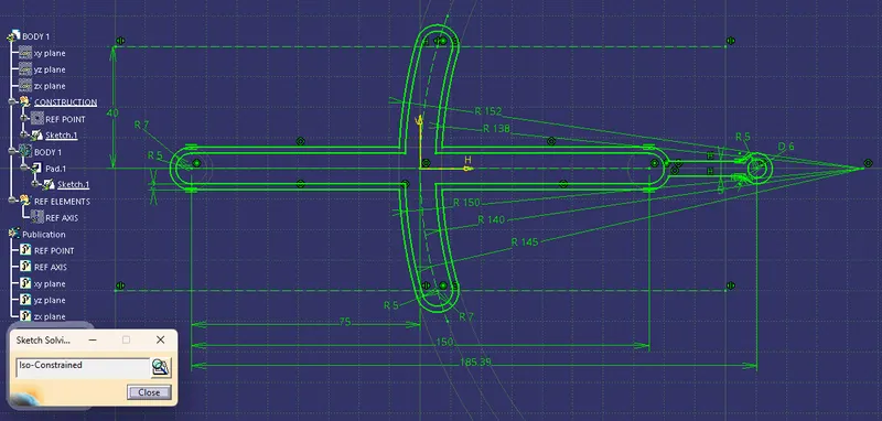
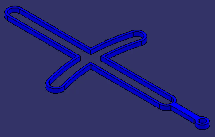
BODY 2:
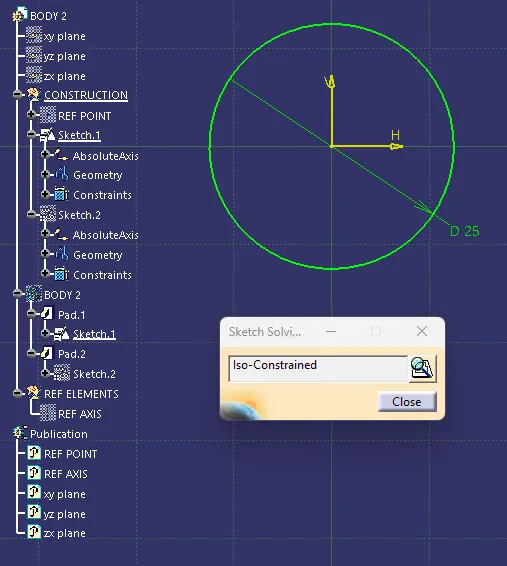
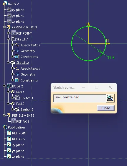
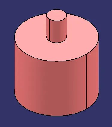
BODY 3:
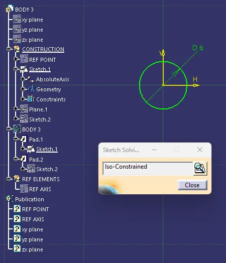
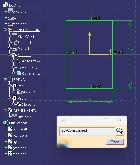
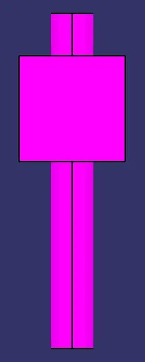
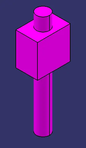
BODY 4:
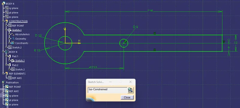
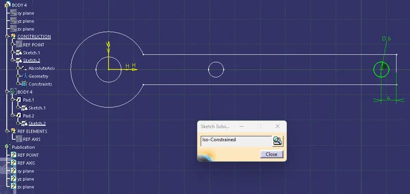
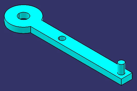
BODY 5:
FINAL ASSEMBLY:
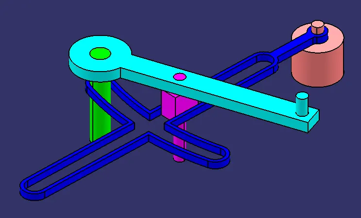
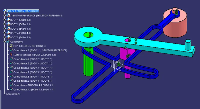
The final assembly of all the parts to form the Quick Return Mechanism as shown below is done in the assembly workbench by using the 'Move' and 'Constraints' toolbars. A new part called the Skeleton Reference with a reference point is created and fixed to act as the refernce for constraining other parts.
(B) ASSEMBLY 2 (CV JOINT):
The given 2D drawings for the CV Joint consists of 3 unique parts. They are modelled individually in part design and are imported to assembly workbench to assemble them together.
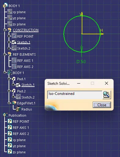
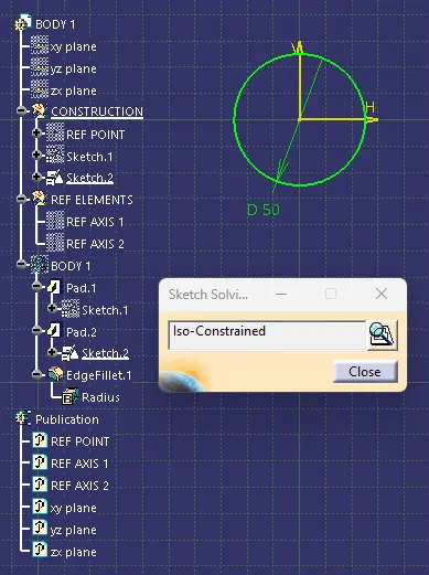
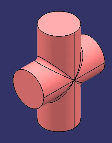
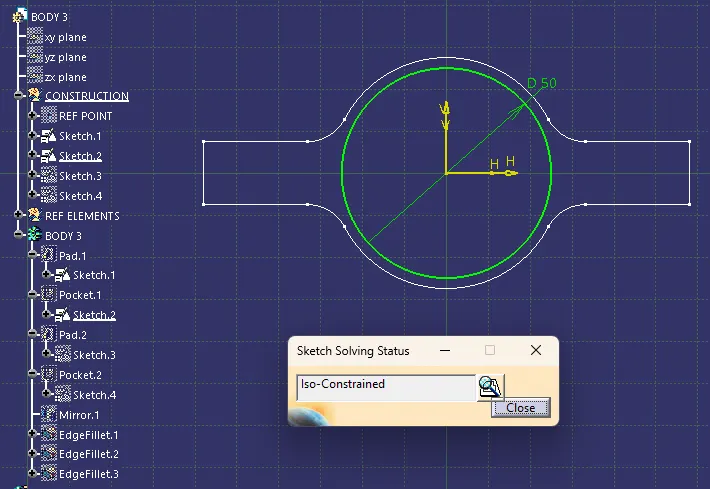
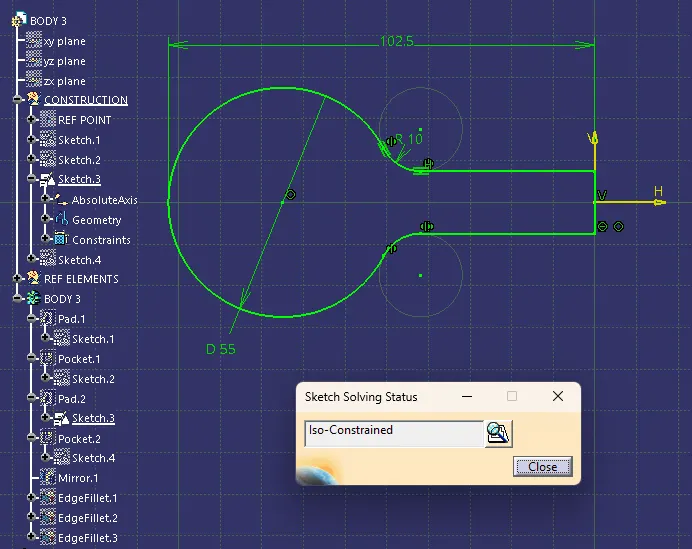
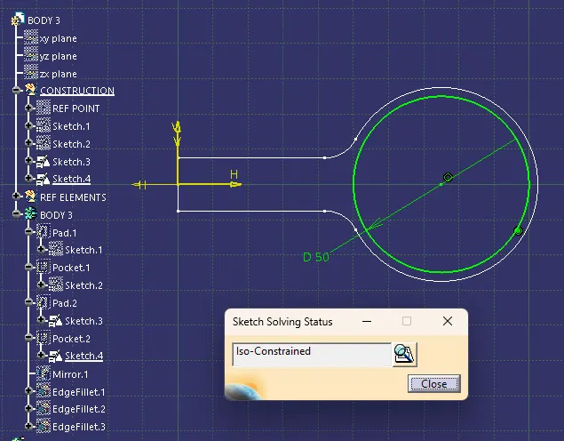
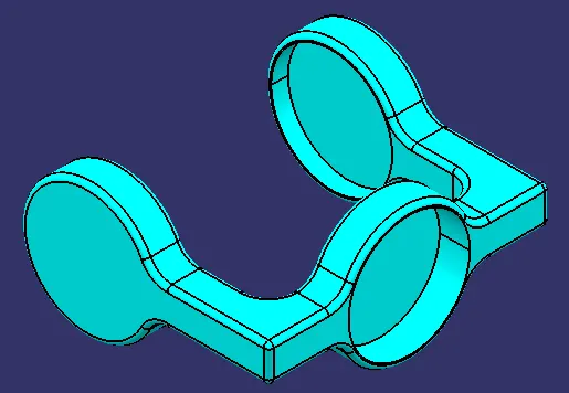
The 3D models along with the 2D sketches and the sketch solving statuses of the parts are shown below:
BODY 1:
BODY 2:
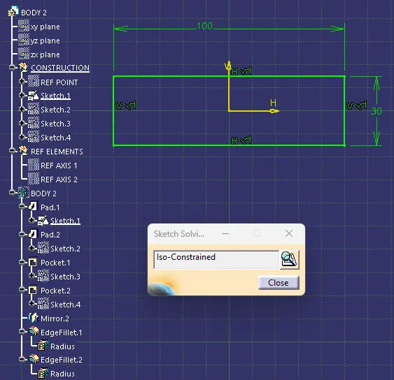
BODY 3:

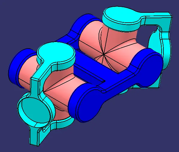
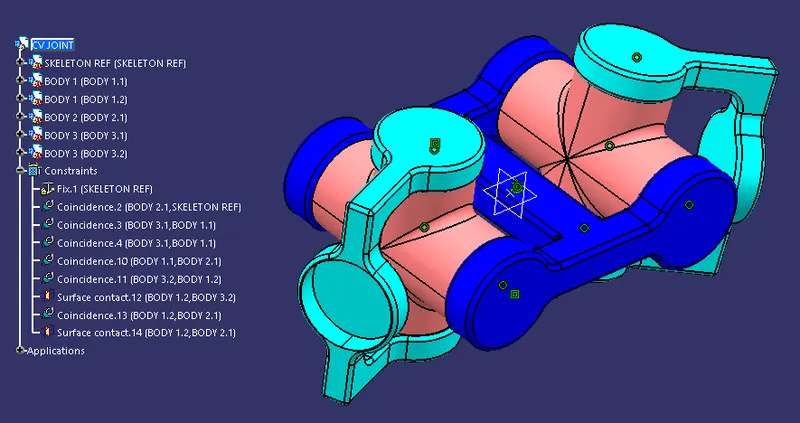
FINAL ASSEMBLY:
The Final Assembly of all the parts to form the CV Joint is done by importing the individual part files in the assembly workbench and then using the constraints to place them together. The below images shows the CV Joint Assembly and the constraints used in the assembly.
CV Joint consists of two Body 1's, one Body 2 and two Body 3's i.e., 5 parts in total to form the assembly.
NOTE: All the part models(.CATPart), assembly files (.CATProduct) and the drafting files (.CATDrawing) with drafting pdfs of the two assemblies are attached in the ZIP File folder below for reference.