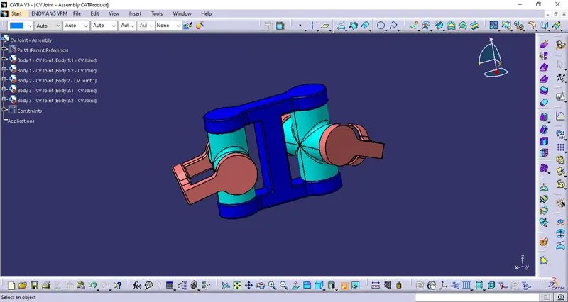
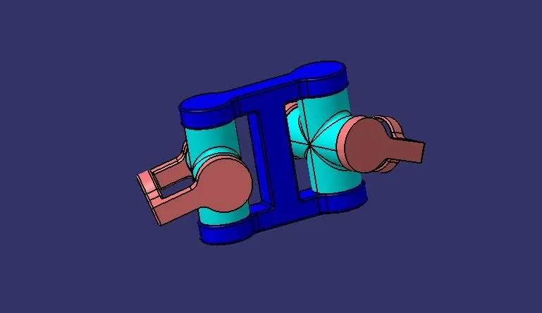
Week 10- Assembly Workbench
*MODEL DRAWING 1:
Design of Part Bodies:
Part Body 1:
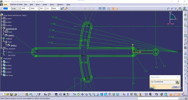
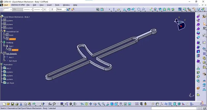
The part body 1 is designed as per the drawing sheet provided.
- Sketching:
- Solid Component:
- Orientations:
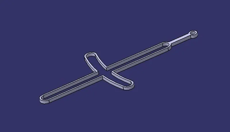
Isometric View:
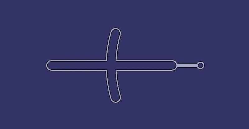
Front View:
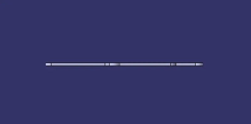
Top View:
Part Body 2:
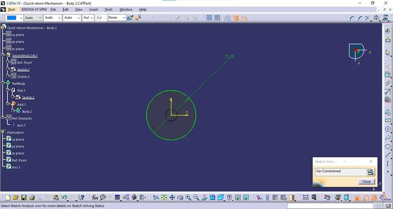
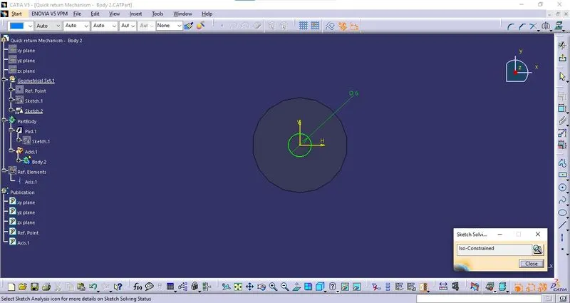
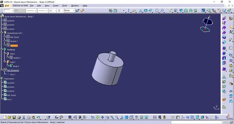
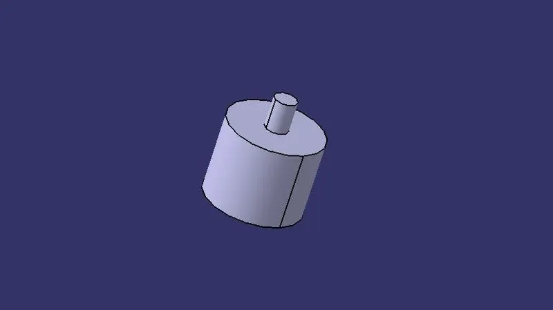
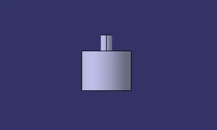
Part body 2 is designed as per the drawing sheet provided.
- Sketching:
- Solid Component:
- Orientations:
Isometric View:
Front View:
Top View:
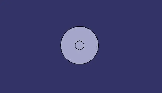
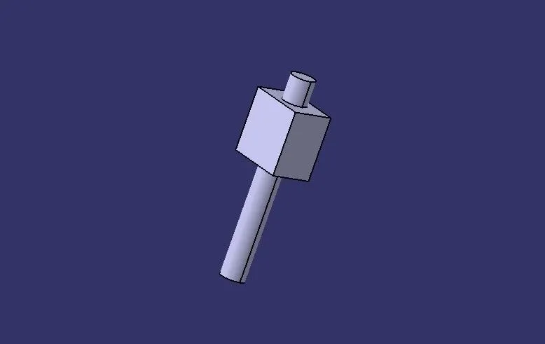
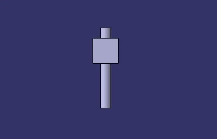
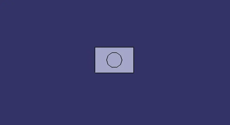
Part Body 3:
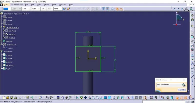
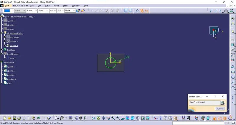
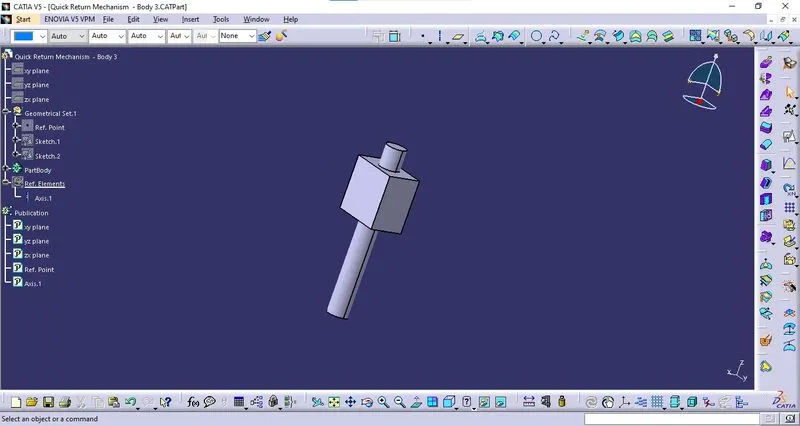
Part body 3 is designed as per the drawing sheet provided.
- Sketching:
- Solid Component:
- Orientations:
Isometric View:
Front View:
Top View:
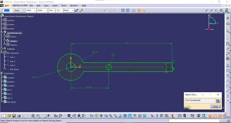
Part Body 4:
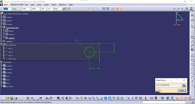
Part body 4 is designed as per the drawing sheet provided.
- Sketching:
- Solid Component:
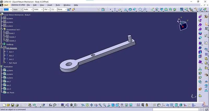
- Orientations:
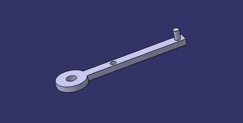
Isometric View:
Front View:
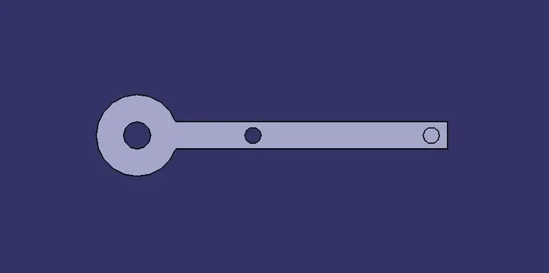
Top View:
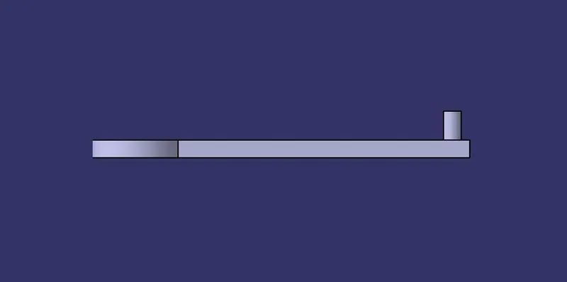
Part Body 5:
Part body 5 is designed as per the drawing sheet provided.
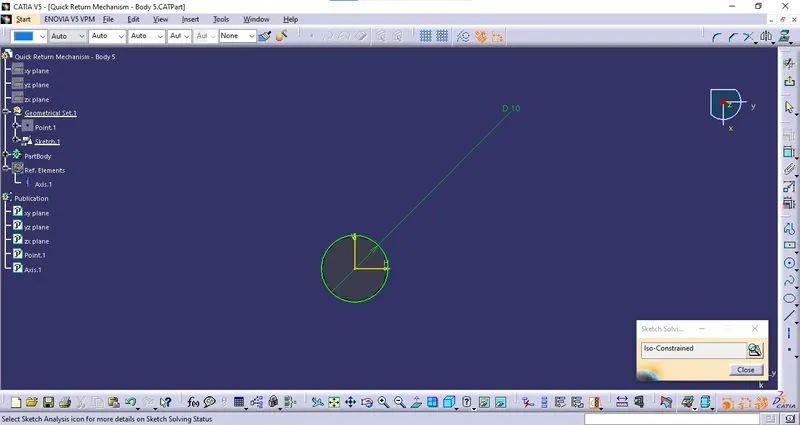
- Sketching:
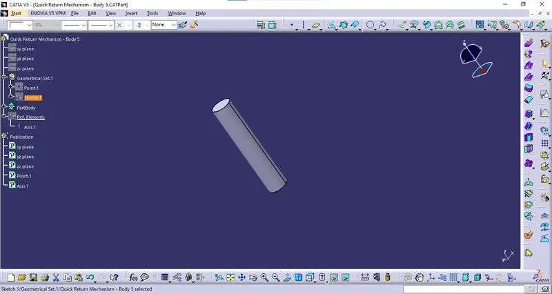
- Solid Component:
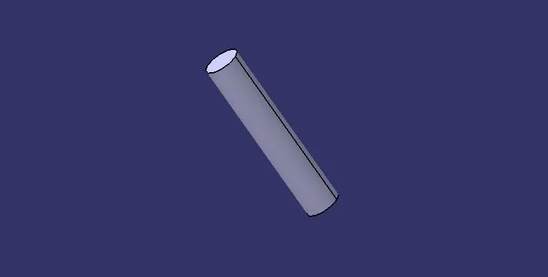
- Orientations:
Isometric View:
Front View:
Top View:

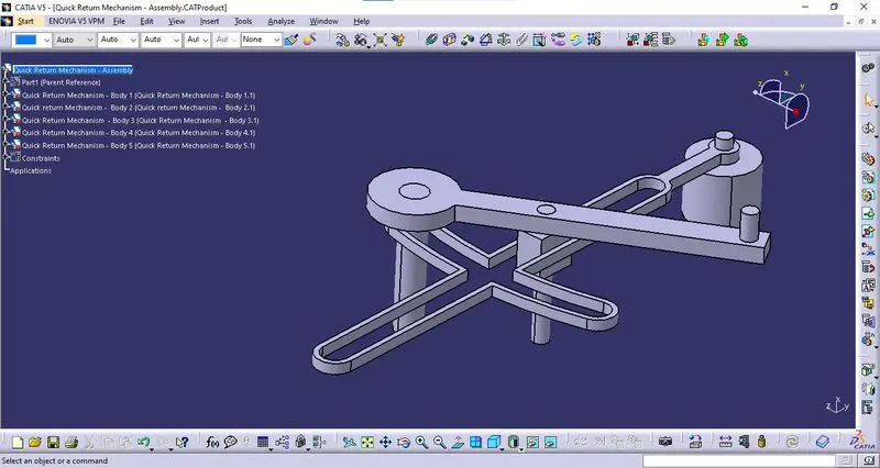
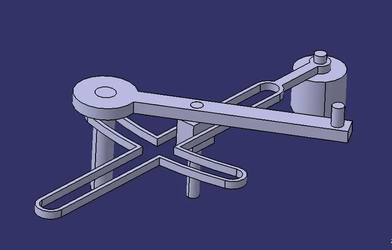
Assembly:
Parent Reference:
The parent reference part was created to define the central axis and planes of the assembly.
Importing Components:
All the below-mentioned components are imported into the assembly using the Existing Part Command or Copy & paste from the Actual Part design.
- Body 1
- Body 2
- Body 3
- Body 4
- Body 5
The reference points, reference axis, and planes are referred to as reference elements and those reference elements were published for every component.
Constraints:
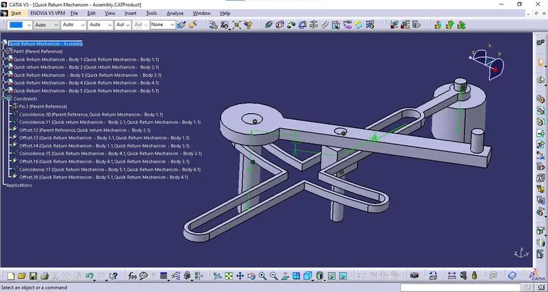
The imported components are constrained using different constraint commands to arrest the degrees of freedom except ones allowed in the constrained movement of the assembly.
- Constraint 1 - Fix:
All degree of freedom of the Parent Reference Part is arrested using the Fix command.
- Constraint 2 - Coincide:
The Reference points from the Body 1 coincided with the reference point from the parent Reference.
- Constraint 3 - Coincide:
The reference axis of the Body 2 coincided with the reference axis from Body 1.
- Constraint 4 - Offset:
A plane from Body 2 is offset with a plane from the Parent reference.
- Constraint 5 - Offset:
A plane from Body 3 is offset with a plane from Body 1.
- Constraint 6 - Offset:
Another plane from body 3 is offset with the respective plane from Body 1.
- Constraint 7 - Coincide:
Reference Axis from Body 4 coincided with the reference Axis from body 3.
- Constraint 8 - Offset:
A plane from Body 4 is offset with a plane from Body 3.
- Constraint 9 - Coincide:
Reference Axis from Body 5 coincided with the reference Axis from body 4.
- Constraint 10 - Offset:
A plane from Body 5 is offset with a plane from Body 4.
Assembly Component:
*MODEL DRAWING 2:
Design of Part Bodies:
Part Body 1:
The part body 1 is designed as per the drawing sheet provided.
- Sketching:
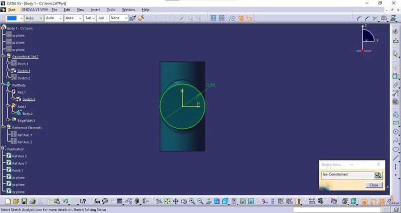
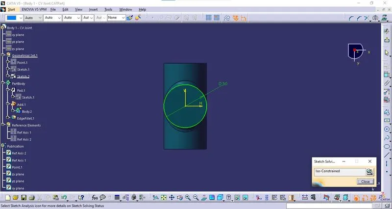
- Solid Component:
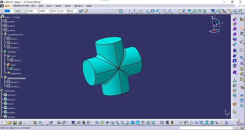
- Orientations:
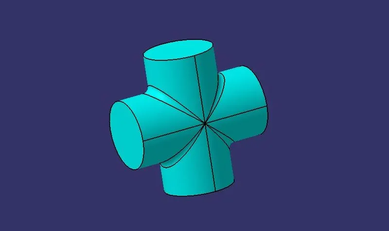
Isometric View:
Front View:
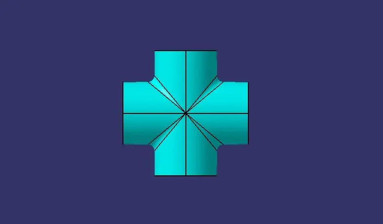
Top View:
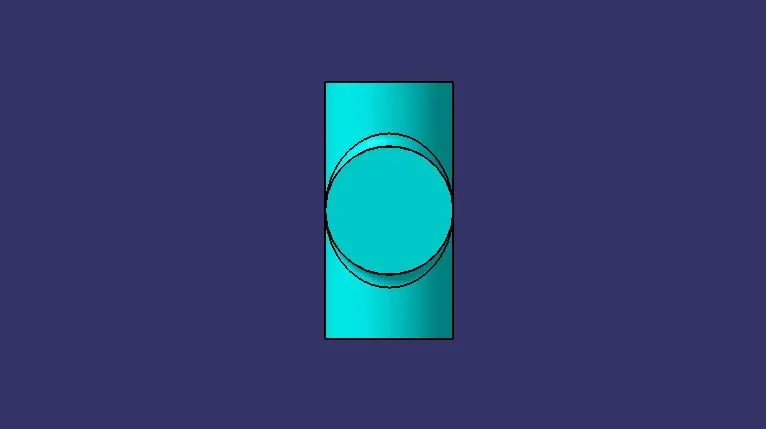
Part Body 2:
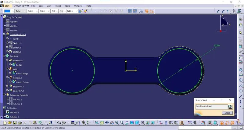
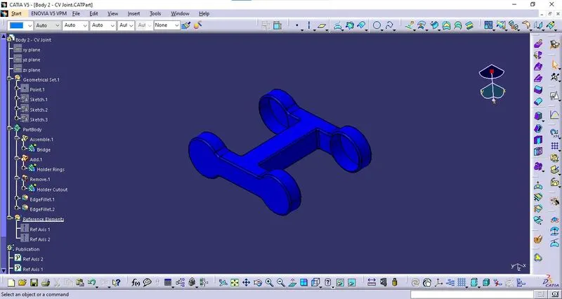
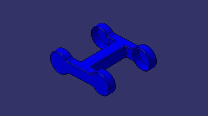
Part body 2 is designed as per the drawing sheet provided.
- Sketching:
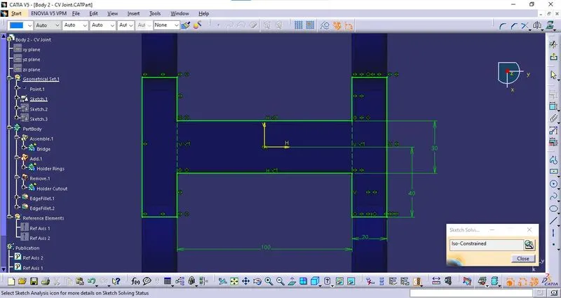
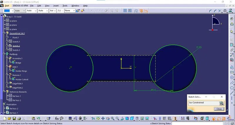
- Solid Component:
- Orientations:
Isometric View:
Front View:
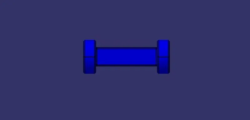
Top View:
Part Body 3:
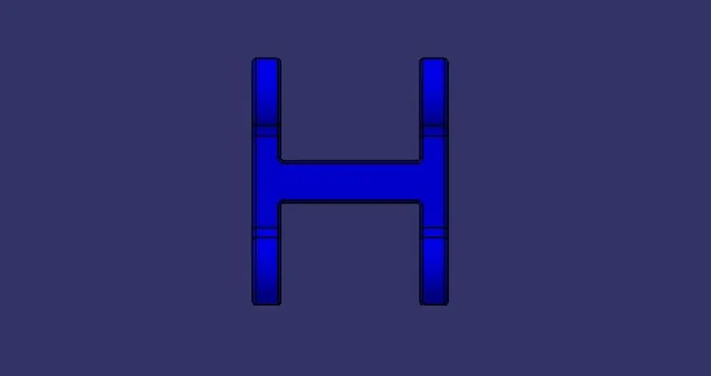
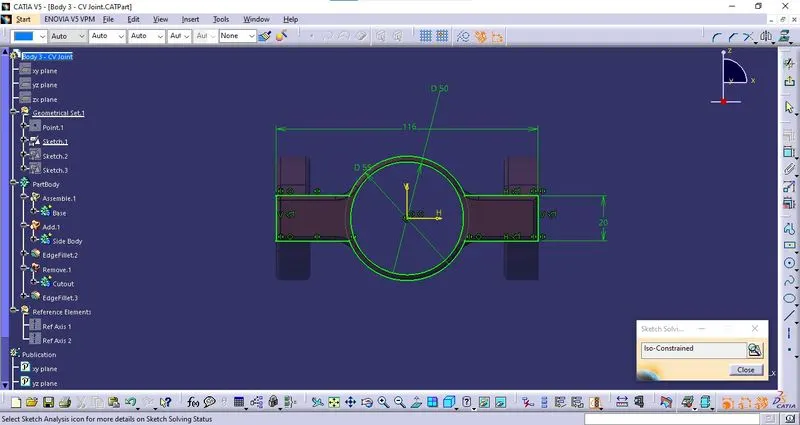
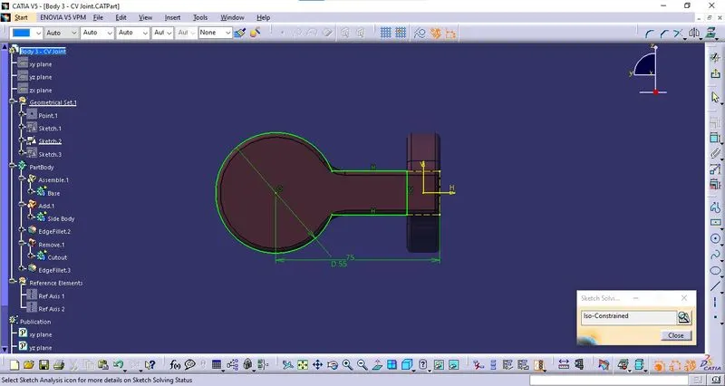
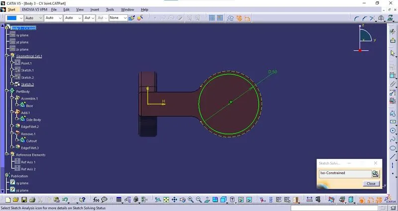
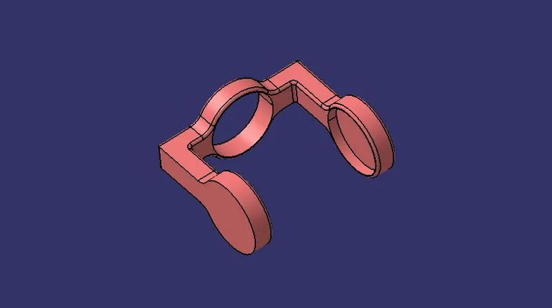
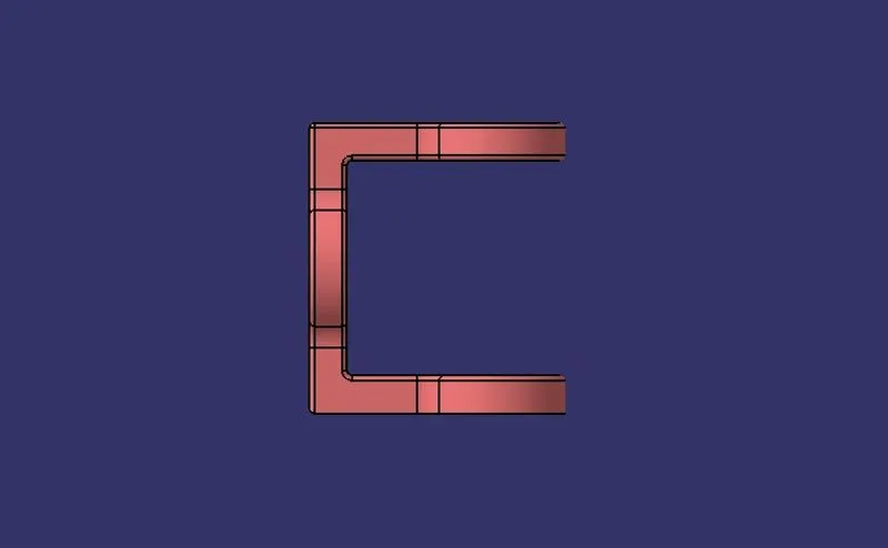
Part body 3 is designed as per the drawing sheet provided.
- Sketching:
- Solid Component:
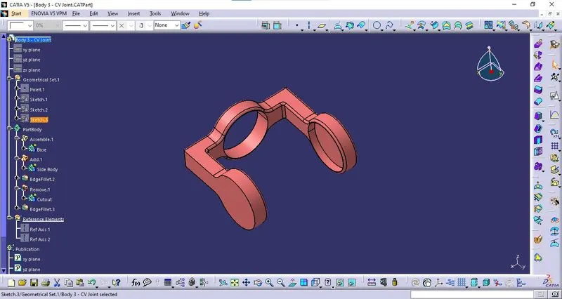
- Orientations:
Isometric View:
Front View:
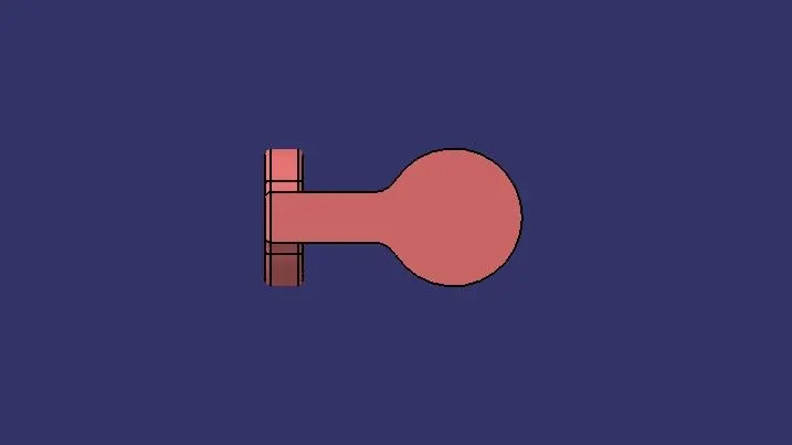
Side View:
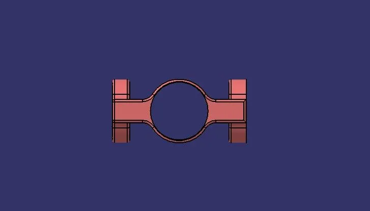
Top View:
Assembly:
Parent Reference:
The parent reference part was created to define the central axis and planes of the assembly.
Importing Components:
All the below-mentioned components are imported into the assembly using the Existing Part Command or Copy & paste from the Actual Part design.
- Body 1.1
- Body 1.2
- Body 2
- Body 3.1
- Body 3.2
The Components Body 1 & Body 3 have been imported twice for assembly purposes since they are used twice.
The reference points, reference axis, and planes are referred to as reference elements and those reference elements were published for every component.
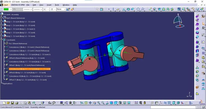
Constraints:
The imported components are constrained using different constraint commands to arrest the degrees of freedom except ones allowed in the constrained movement of the assembly.
- Constraint 1 - Fix:
All degree of freedom of the Parent Reference Part is arrested using the Fix command.
- Constraint 2 - Coincide:
The Reference points from the Body 2 coincided with the reference point from the parent Reference.
- Constraint 3 - Coincide:
A plane from Body 2 coincided with a plane from the Parent reference.
- Constraint 4 - Coincide:
Reference Axis from Body 1.2 coincided with the reference Axis from Body 2.
- Constraint 5 - Offset:
A plane from Body 1.2 is offset with a plane from Parent Reference.
- Constraint 6 - Coincide:
Reference Axis from Body 1.1 coincided with the reference Axis from Body 2.
- Constraint 7 - Offset:
A plane from Body 1.1 is offset with a plane from Parent Reference.
- Constraint 8 - Coincide:
Reference Axis from Body 3.1 coincided with the reference Axis from Body 1.1.
- Constraint 9 - Offset:
A plane from Body 3.1 is offset with a plane from Body 1.1.
- Constraint 10 - Coincide:
Reference Axis from Body 3.2 coincided with the reference Axis from Body 1.2.
- Constraint 11 - Offset:
A plane from Body 3.2 is offset with a plane from Body 1.2.
Assembly Component: