Week 10:- 2D Detailing Challenge
2D DETAILING OF FIXTURE UNITS
INTRODUCTION
The fixture design before going to the manufacturing department needs to be detailed clearly and accurately. All the dimensions to fabricate the fixture units have to mention in the drawing sheets. There are different drawing sheets available as per the company requirements. As per the customer given data, all the details must be provided.
The 2D detailing must be as per the engineering drawing data. First or third angle projections are to be implemented. The top view, right side view, and front view must be given with all the dimensions. The isometric view must be provided with the part name and details.
GD &T must be applied where ever it is required to minimize the cost of the production. Tolerances must be provided.
OBJECTIVE
The objective is to 2D detail the base unit, pin unit, and complex unit by applying all the views and dimensions in CATIA V5.
2D DETAILING OF FIXTURE UNIT
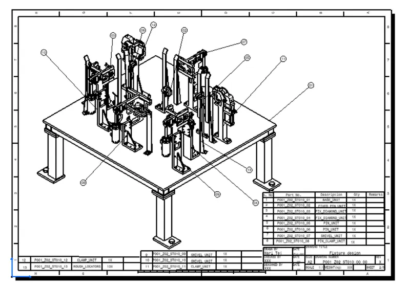
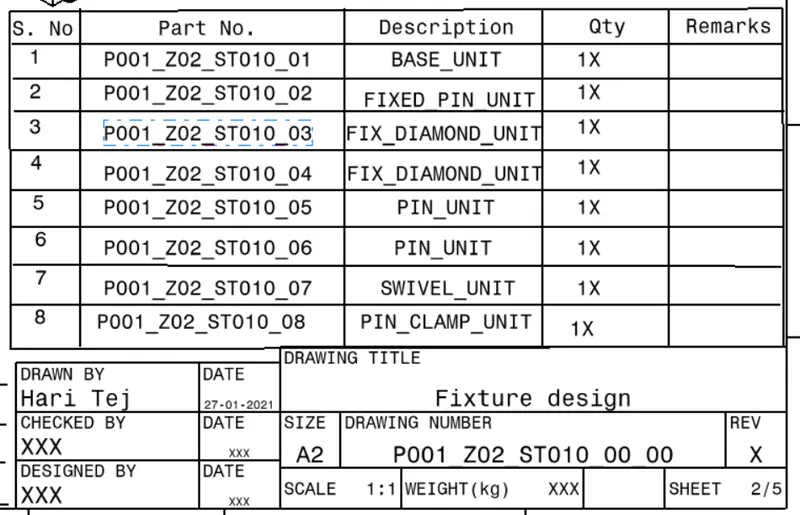
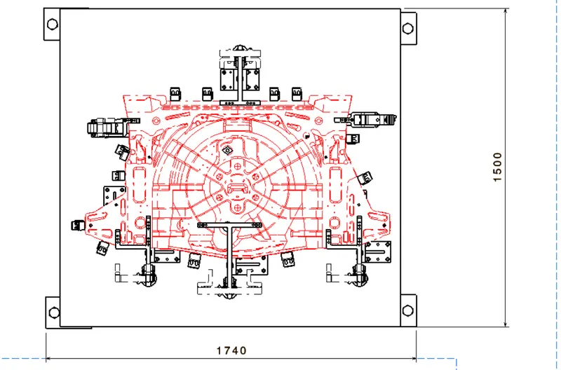
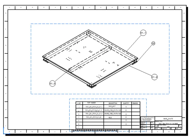
The fixture unit has to be detailed clearly with all the view in drawing sheets. The part number and details are to be provided in the isometric view. The details can be provided in the customer's prescribed manner. In the present detailing, a detail box is made near the index with all the unit numbers.
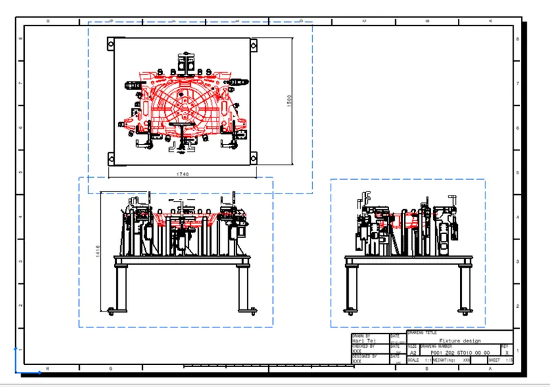
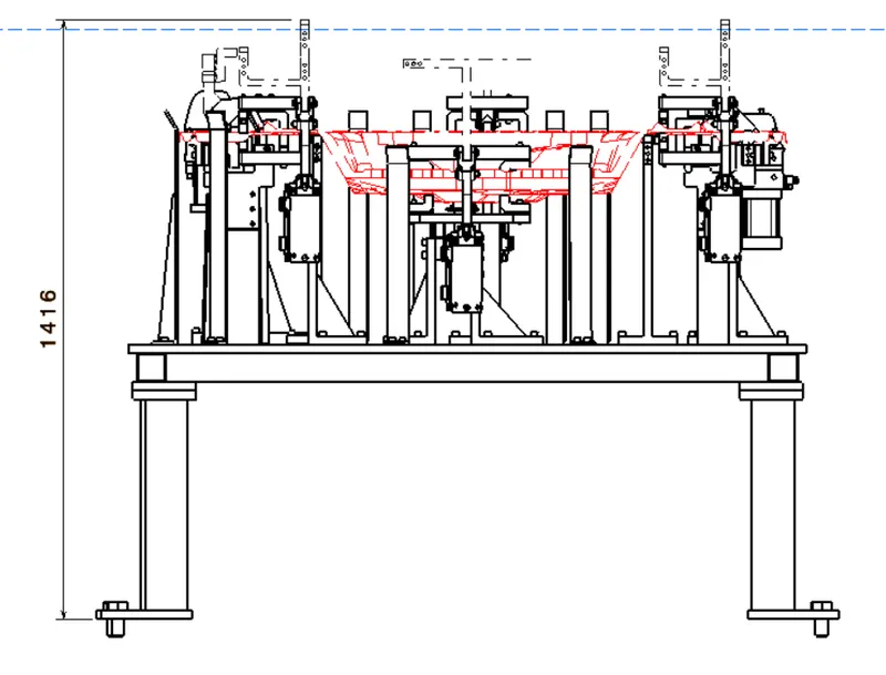
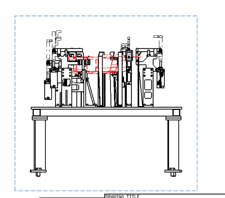
The top view, front view, and side views are to be detailed in another sheet. The overall lengths of the fixture are to be provided. The open condition must be marked as dotted lined. The panel can be shown in red color so the manufacturer can easily understand the drawing.
2D DETAILING OF BASE UNIT
The base unit with square tubes, base plate, and rough locators must be detailed in the drawing sheet.
The overall base unit is taken in all the views along with isometric views. Each child part has to be detailed clearly.
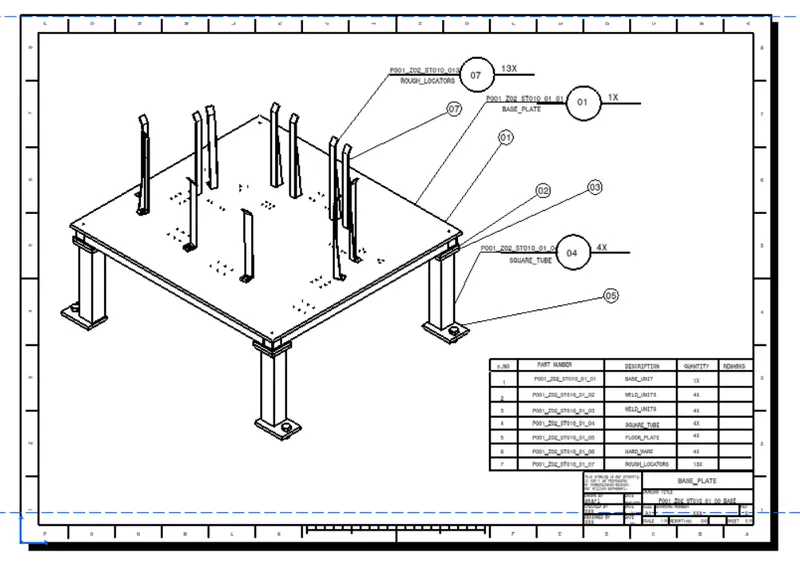
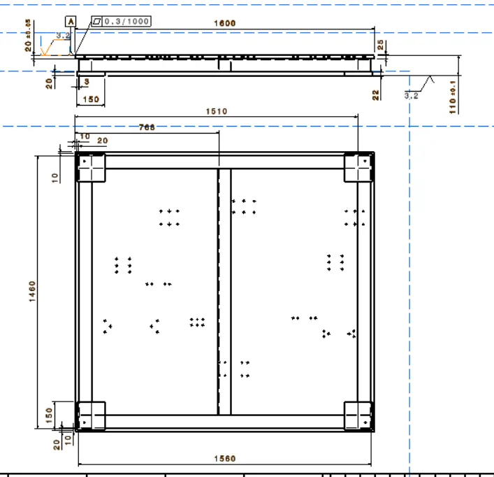
In the base plate, all the details along with tolerance values are provided.
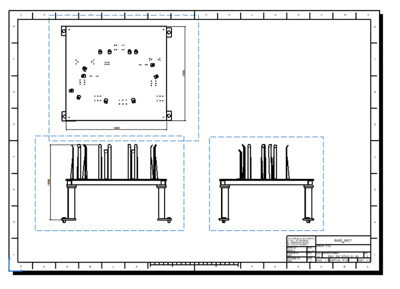
Note: Where ever the surface has to be smooth, a surface roughness value of 3.2 is provided. This value depends on the customer's requirements.
An extra surface must be shown such that the manufacturer can take the raw material with that dimensions and cut it to the required dimensions.
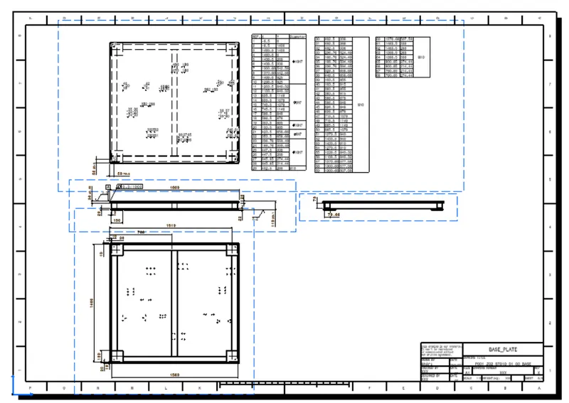
Where ever it is required, tolerance values must be provided. The customer gives this tolerance value.
In the base plate, the holes data are to be provided as per the CNC machine conditions. The tooling hole is taken as the starting hole condition, and the holes must be according to it. All the dowel holes are drilled once, and the threaded holes are drilled next.
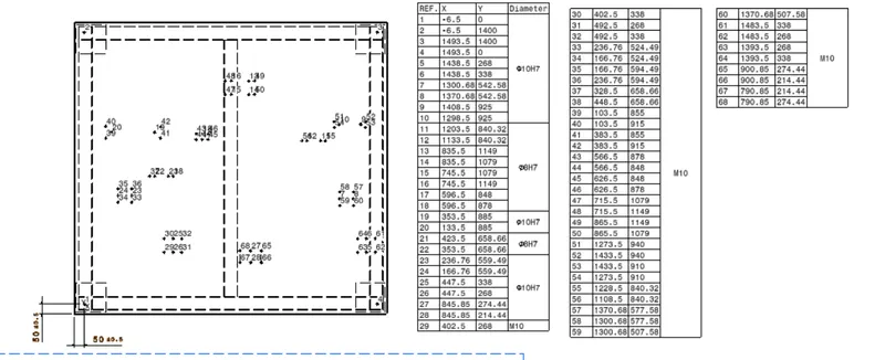
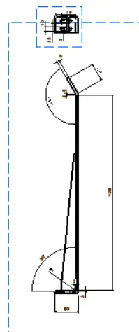
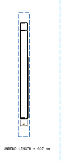
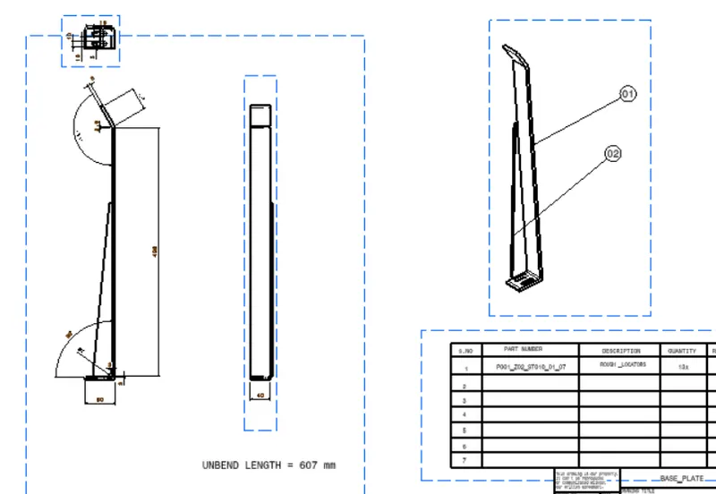
Note: All the holes must be nominal. It is advised to drill the holes manually if any decimal points are available.
All the dimensions must be nominal.
2D DETAILING OF PIN UNIT
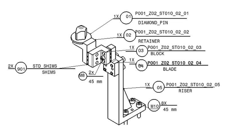
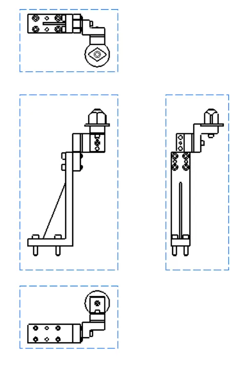
The 2D detailing of the pin unit with a diamond pin is provided with all the details. All the child parts are shown with part numbers in the isometeric view.
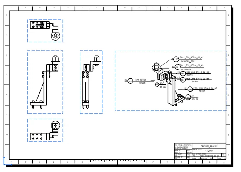
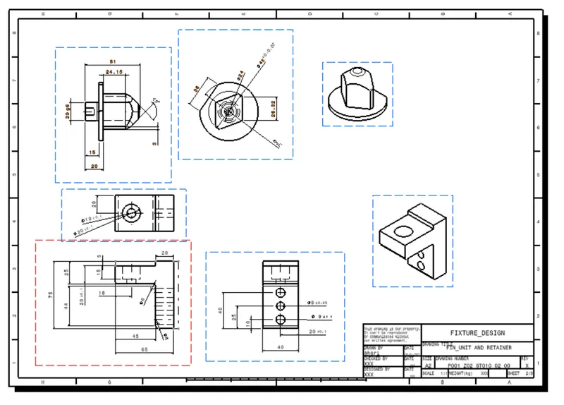
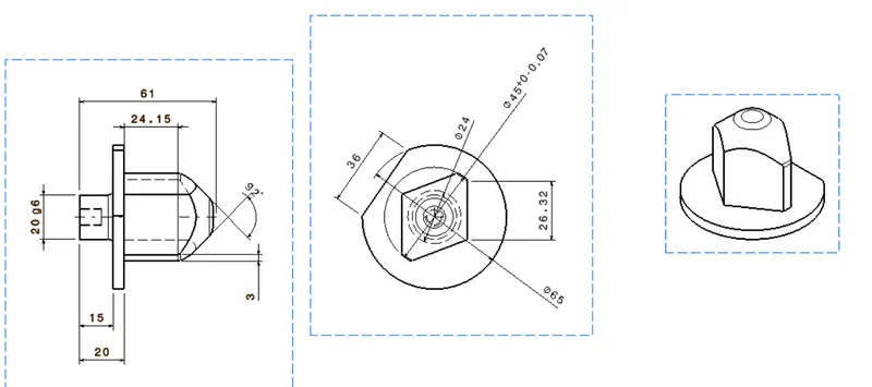
The 2D detailing of diamond pina nd retainer.
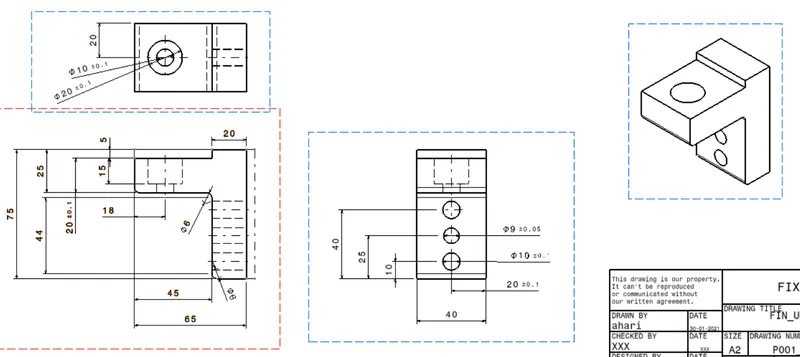
The 2D detailing of L-block and blade.
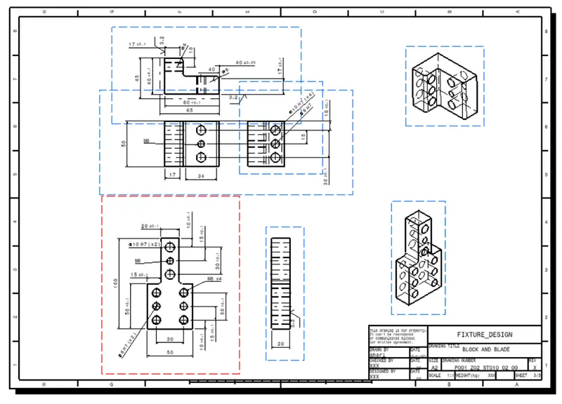
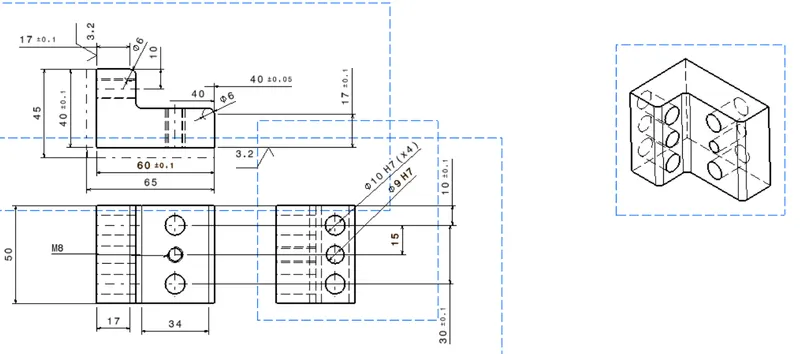
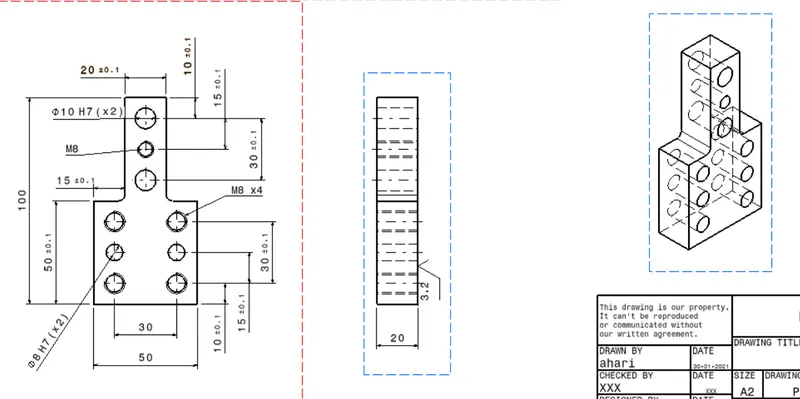
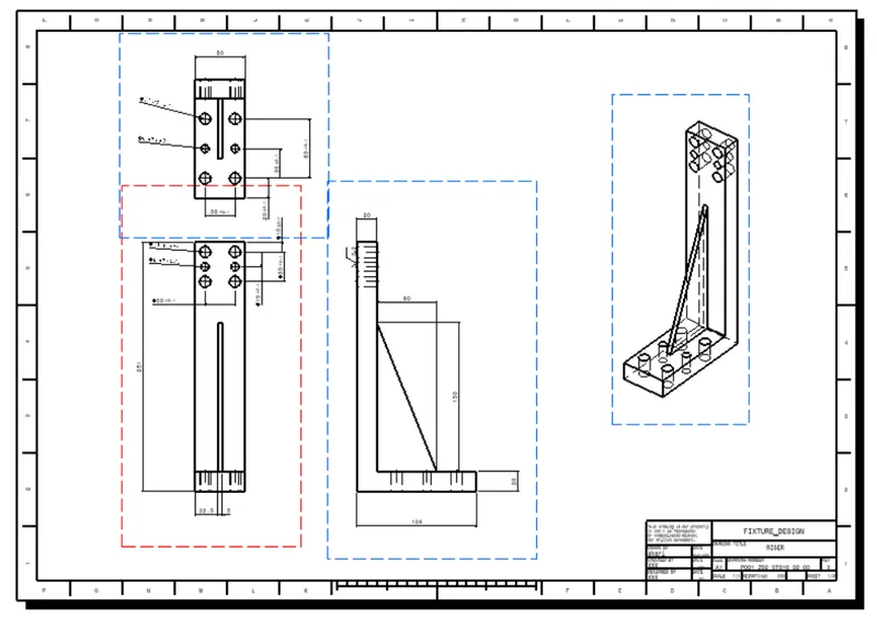
The 2D detailing of the riser.
Note: The shims are standard in all the units so the shim's names will be given as Standard shims.
CONCLUSION
The 2D detailing of the fixture unit, base unit, pin unit, and complex pin unit is provided with all the child parts' detailing.