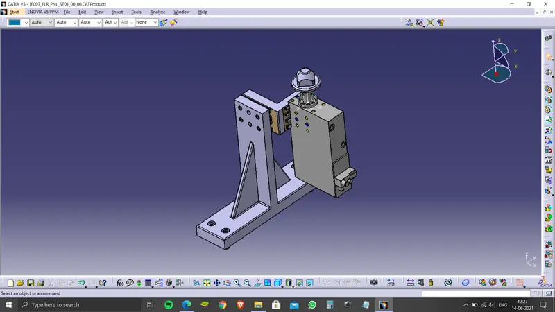
Week 10:- 2D Detailing Challenge
AIM:
To draft a Key sheet, Base unit, and Fix pin unit designs with all required child parts.
SOFTWARE:
CATIAV25
INTRODUCTION:
Body in white (BIW) refers to the stage in automobile manufacturing in which a car body's components have been joined together, using one or a combination of different techniques: welding (spot, MIG/MAG), riveting, clinching, bonding, laser brazing, etc. BIW is termed before painting and before the motor, chassis sub-assemblies, or trim (glass, door locks/handles, seats, upholstery, electronics, etc.) have been assembled in the frame structure.
In order to manufacture such parts fixtures are used. These fixtures once modelled go through a process of 3D finishing and finally drafting based on required GD&T.
GEOMETRIC DIMENSIONING AND TOLERANCING:
Geometric Dimensioning and Tolerancing (GD&T) is a system for defining and communicating engineering tolerances. It uses symbolic language on engineering drawings and computer-generated three-dimensional solid models that explicitly describe nominal geometry and its allowable variation. It tells the manufacturing staff and machines what degree of accuracy and precision is needed on each controlled feature of the part. GD&T is used to define the nominal (theoretically perfect) geometry of parts and assemblies, to define the allowable variation in form and possible size of individual features, and to define the allowable variation between features.
DRAFTING:
Drafting, also spelt draughting, also called engineering drawing, graphical representation of structures, machines, and their component parts that communicates the engineering intent of a technical design to the craftsman or worker who makes the product.
At the design stage, both freehand and mechanical drawings serve the functions of inspiring and guiding the designer and of communicating among the designer, collaborators, production department, and marketing or management personnel. At this stage, exact mechanical drawings can clarify, confirm, or disqualify a scheme that looked promising in a freehand sketch. Actually, both the sketch and the exact mechanical drawing are essential parts of the process of designing, and both belong to the field of drafting. After the basic design has been established, drafting skills aid in the development and transmission of the wealth of data necessary for the production and assembly of the parts. For an automobile, a skyscraper, or a spacecraft, tens of thousands of drawings may be needed to convey all of the requirements of the finished product from the designers to the fabricators.
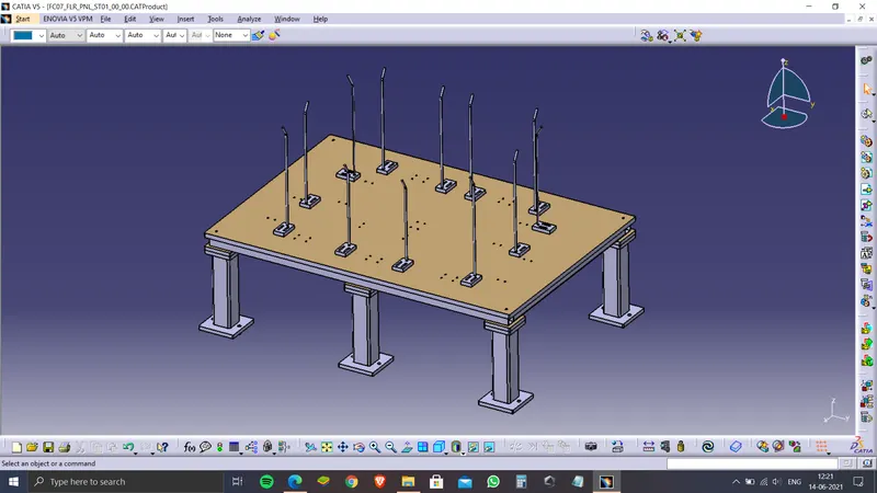
BASE UNIT:
A base unit is a steel or aluminium plate of 20-40mm to which all other pin and clamp units are attached. It must also provide space for parts like a pneumatic controller, eye bolts, pneumatic cable trunking paths etc.
DESIGN FUNDAMENTALS OF BASE PLATE DESIGN:
- The Base unit should enclose all the units to the periphery including in the open position.
- The Baseplate should be designed as per BCS coordinates.
- It should have datum holes and measuring holes with a pitch of 1000mm in general.
- Depending on the size of the plate the number of holes may vary.
- Datum holes should be places at nominal positions like X=150, Y=120, Z=380
- Datum holes should be at least 100mm from other units
- Datum holes should be covered with cover plates.
PIN UNIT:
A pin unit is used to locate a component in a fixture, they can be separated based on the ability of motion of the pin as a fixed and retractable pin unit. The pin unit stops the motion of the component along a certain axis.
A fixed pin unit consists of a riser, blades, shims, pin retainer and pin.
- Riser: It’s the part used to change the height of the whole unit.
- Blades: These are plates mounted on the riser to which other parts like cylinders, arms etc are mounted.
- Shims: These are parts that are used to compensate for the stack-up tolerances of the mylars. They vary in thickness by 0.1mm, 0.2mm, 0.5mm etc.
- Pin and pin retainer: The pin which is fixed to the pin retainer
The primary purpose of this unit is to locate the panel using the pin. It restricts the degrees of freedom of the panel using the 3-2-1 principle.