Week 1 Stress Concentration on a Plate with hole
OBJECTIVE
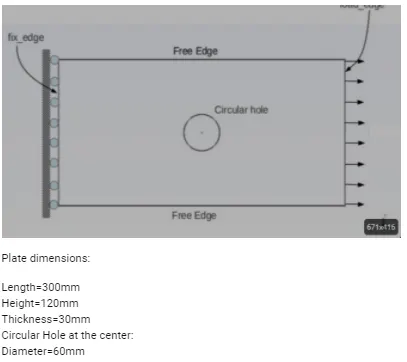
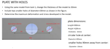
Design a Plate with a hole in the center and perform a static structural simulation using Ansys. Discuss the results for the below 2 cases with Boundary condition as left face fixed and a load of 500 N acting on the right face (Pull)
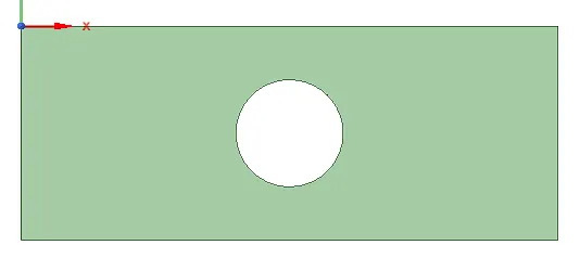
CASE 1 - Plate with a hole in the center
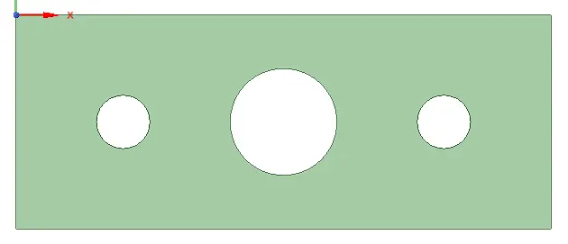
Case 2 - Plate with multiple holes
Outputs
- Compare the deformation and maximum stresses in both the cases
- Explain which model to use from an analysis perspective.
- Explain which model to use from a manufacturing perspective
PROCEDURE
There are two cases to be discussed here and steps used in building both the simulation is discussed below.
Step 1 - Geometry
- Open Spaceclaim from Wokebench -> Static structural window.
- Create a 2D geometry using Spaceclaim.
- Select the Pull option to assign a thickness of 30mm.
Step 2 - Material Assignment
- Open Engineering Materials and select the required material.
- Structural steel is a default material in ANsys
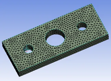
Step 3 - Meshing
- Mesh -> insert -> method -> method = tetrhedrons
- Element size = 7 mm
Step 4 - Boundary Condition
- Fixed support on left side
- The force of magnitude 500 on the right side
Step 5 - Solution
- Extract deformation, Equivalent stress, and equivalent strain.
RESULTS
| CASE -I Plate with single hole | Case 2 - Plate with multiple holes | ||
| Geometry |
|
|
|
| Mass |
7.8121 kg |
7.4792 kg |
|
| Mesh | 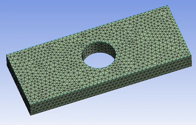 |
 |
|
| Mesh Quality | 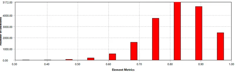 |
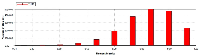 |
|
| Boundary Condition | 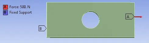 |
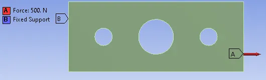 |
|
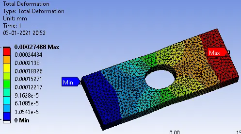
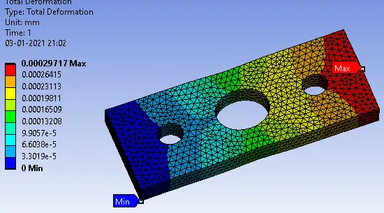
| Deformation |
max deformation = 0.00027488 mm |
Max deformation = 0.00029 mm |
|
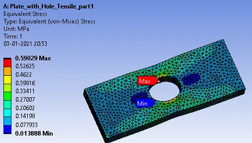
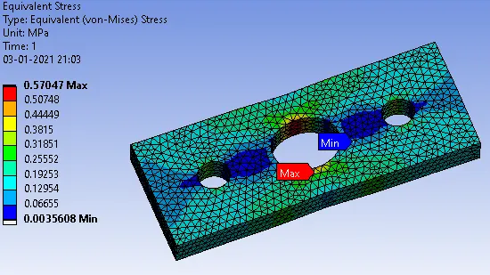
| Equivalent Stress |
max stress = 0.59029 MPa |
max stress = 0.57047 MPa |
|
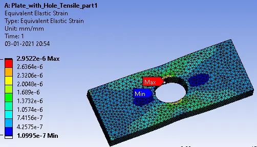
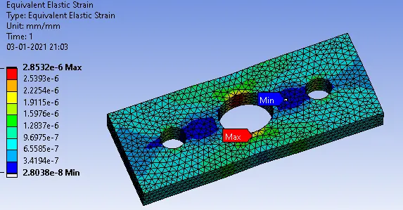
| Equivalent Strain |
Max strain = 2.9522 e-6 |
Max strain = 2.8532e-6 |


CONCLUSION
Based on the static structural simulation done for both the cases, deformation, stress, and strain were compared. based on these results we can conclude the following things
- From an analysis standpoint, case 2 is preferable since max stress and strain are less compared to case 1 for the same loading condition. This is caused by additional holes that act as a stress reliever in this model. So it can be subjected to more load if required. Also, the mass is less in Case 2 compared to case 1 which gives the possibility of reducing material cost and lighter object.
- From a Manufacturing standpoint, case 1 is preferable as the making of additional two holes requires additional operations to be performed which requires additional time.