Week 1 Stress Concentration on a Plate with hole
Case :1
Design a plate with a hole model.
Determine the maximum deformation and stress developed in the model.
Plate dimensions:
Length=300mm
Height=120mm
Thickness=30mm
Circular Hole at the center:
Diameter=60mm
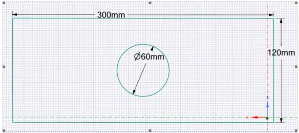
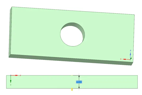
The plate is designed as asked in case 1 as shown above.
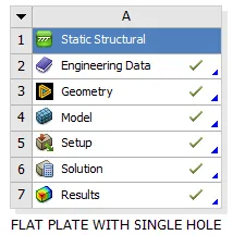
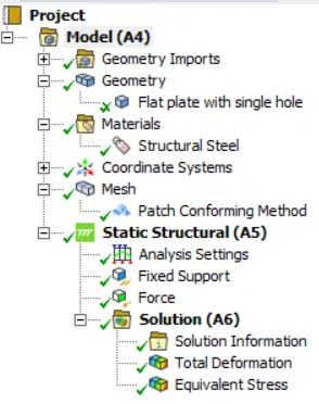
Material used: structural steel
Mesh:
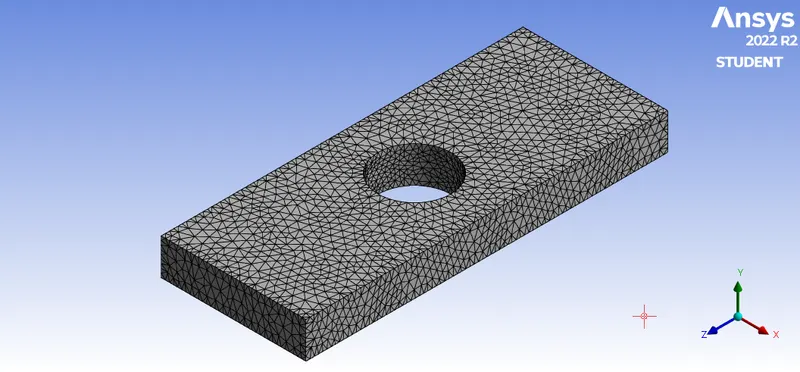
Mesh quality:
- Details of the mesh: Considered Tetrahedron mesh of element size 3.5mm
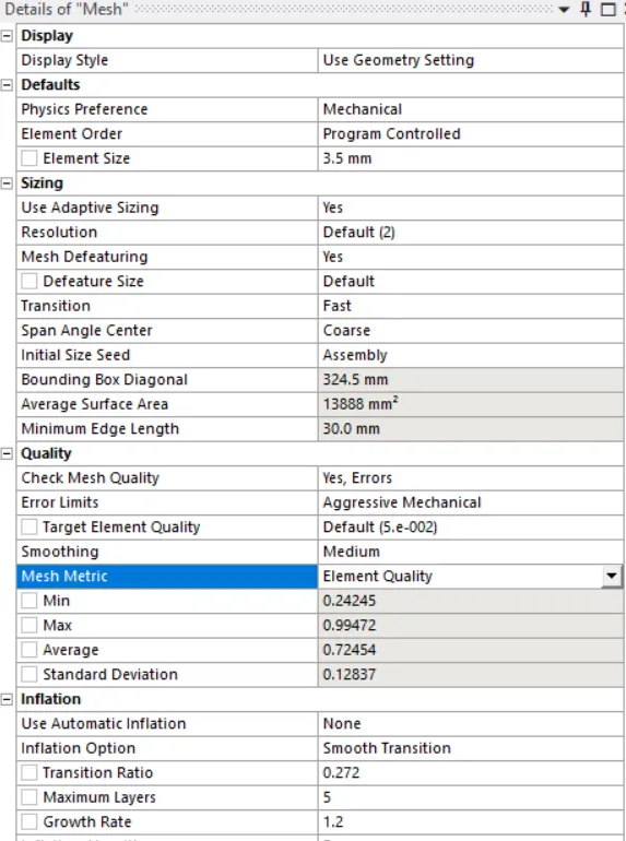
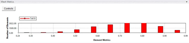
Quality:
- The quality of the mesh looks good.
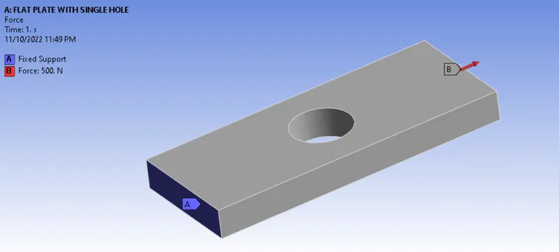
Boundary condition:
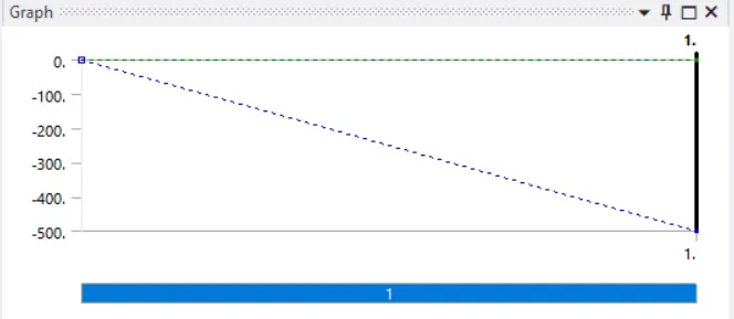
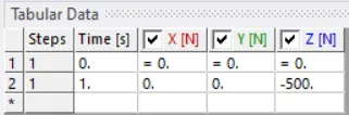
- Fixed support at one end of the plate and tension of 500N is applied on the other end. the analysis is done for time step:1s
Results:
Total deformation:
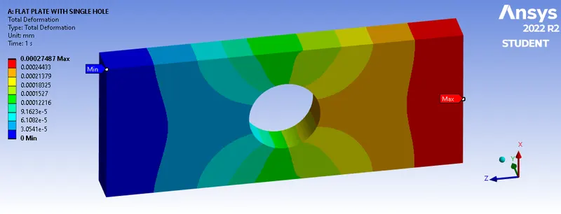
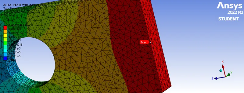
- The total deformation on a plate with a single is shown above as are the global image and zoom image. The zoomed view shows the location of maximum deformation.
- The maximum deformation is seen on the side where tension is applied whereas the minimum is seen near the regions of fixed support.
- The maximum deformation is 0.00027mm which is very less. No deformation is seen near the fixed support.
Von-mises stress:(equivalent stress)
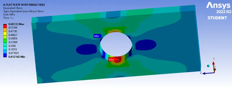
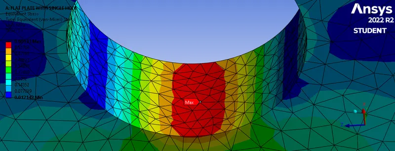
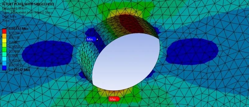
- As shown in the image, the stress is maximum in the plate near the inner face of the hole. This is due to the high-stress concentration in this region.
- The hole in the plate causes a sudden change in the stress line due to which high-stress concentration is seen near the hole region.
- The maximum stress is 0.603Mpa and the minimum is 0.012Mpa
- The stress lines if drawn for the above plate will clearly explain the reason why the stress is maximum and minimum in that location.
Case 2:
Model:
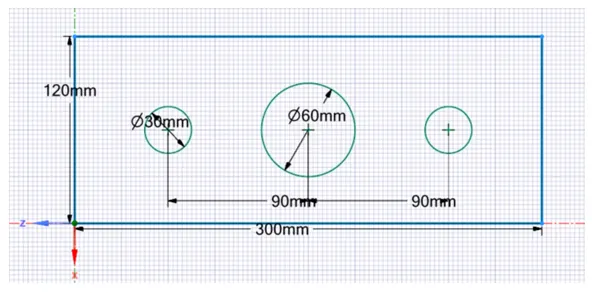
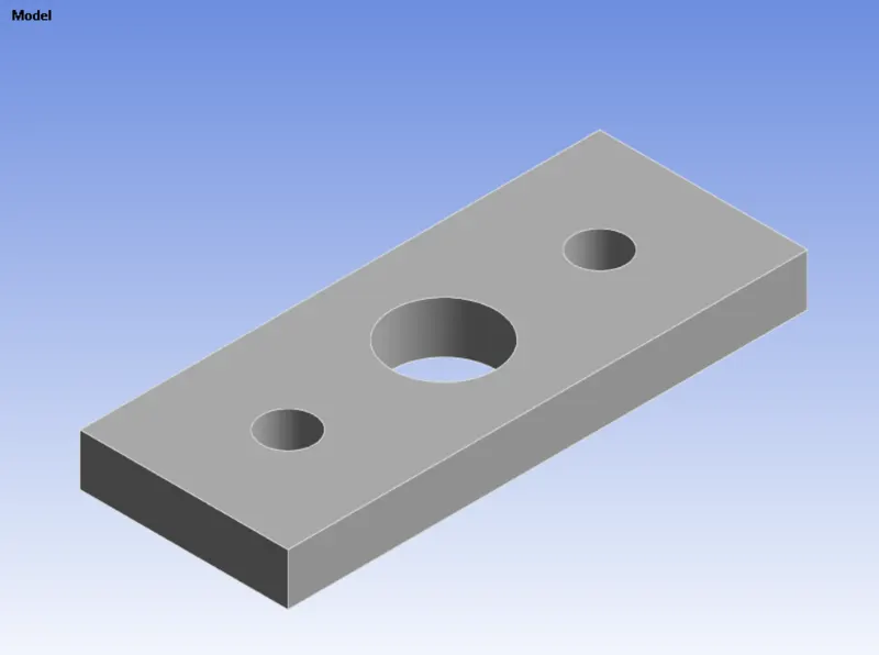
Material used: structural steel
Mesh:
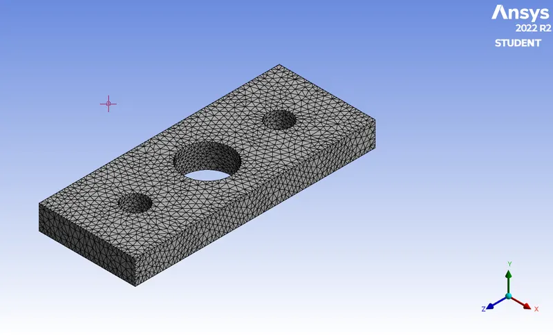
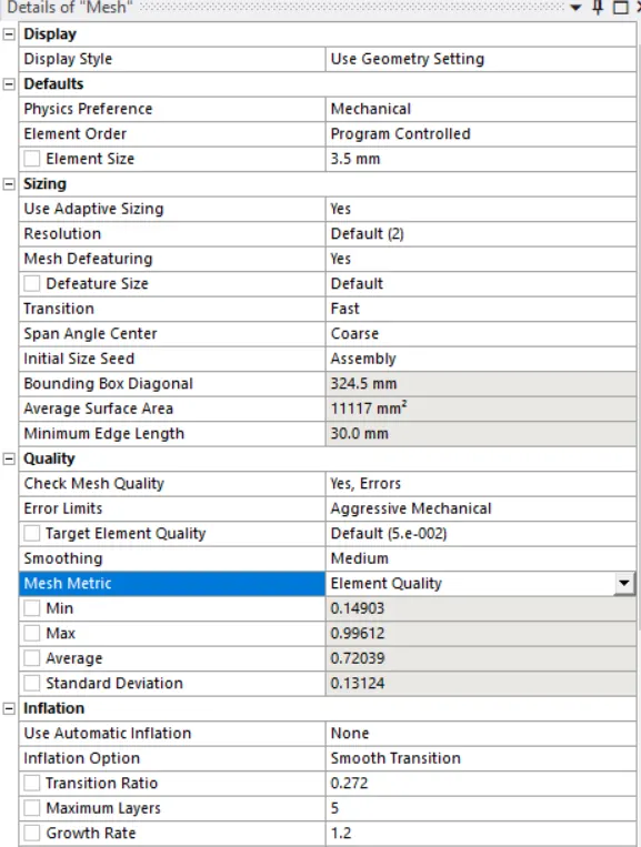
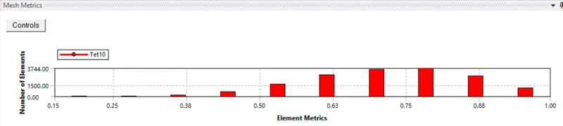
Mesh quality:
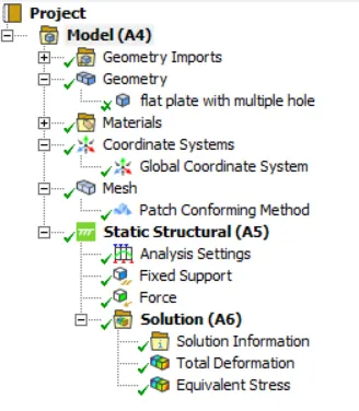
- Details of the mesh: Considered Tetrahedron mesh of element size 3.5mm here also.
Boundary condition:
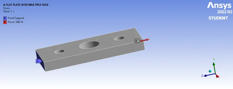
- Fixed support at one end of the plate and tension of 500N is applied on the other end. the analysis is done for time step:1s
Results:
Total deformation:
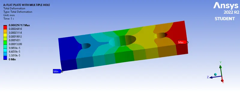
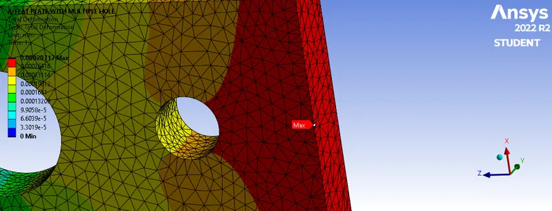
- The total deformation on a plate with a multiple hole is shown above as are the global image and zoom image. The zoomed view shows the location of maximum deformation.
- The maximum deformation is seen on the side where tension is applied whereas the minimum is seen near the regions of fixed support.
- The maximum deformation is 0.00029mm which is very less. No deformation is seen near the fixed support.
Von-mises stress:
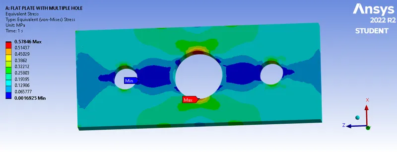
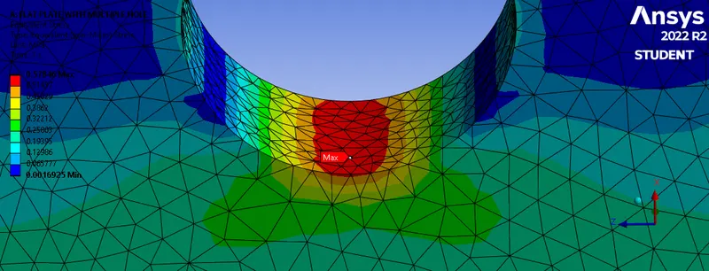
- As shown in the image, the stress is maximum in the plate near the inner face of the hole. This is due to the high-stress concentration in this region.
- The hole in the plate causes a gradual change in the stress line due to which stress concentration is reduced seen near the hole region.
- The maximum stress is 00578Mpa and the minimum is 0.0017Mpa
- The stress lines if drawn for the above plate will clearly explain the reason why the stress is less.
- The small diameter holes near bigger diameter hole helps in reducing the stress concentration by converting sudden change to gradual change of stress lines.
Comparison table for Total deformation:
| Single hole | Multiple hole( big hole and two small holes on sides) |
|
|
The comparison table for both cases shows that deformation in case 2 is more compared to case 1 due to uniform distribution of stress in case 2.
Comparison table for Von-mises stress:
| Single hole | Multiple hole( big hole and two small holes on sides) |
|
|
The comparison table for both cases shows that stress in case 1 is more compared to case 2.
Reason:
- The small diameter holes near bigger diameter hole help in reducing the stress concentration by converting sudden change to gradual change of stress lines due to which the stress in case 2 is less compared to case 1.
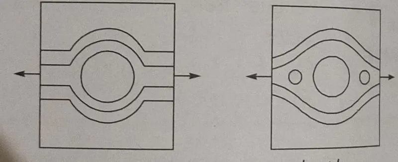
- This image shows how the stress lines are for both plates. This gives a clear idea of why stress values are high in case 1.
- In case 1 due to sudden change in stress lines the values of stress reflecting is high in comparison to case 2.
Selection from an analysis point of view:
- As discussed above since the stress concentration is less in case-2, therefore we will consider Case-2 for our analysis.
- The stress values are less in case-2 compared to case 1, therefore the chances of failure are less for case 2 compared to case 1.
- There is a uniform distribution of stress in case 2
- The deformation is also very small.
Selection from a manufacturing point of view:
- Since case-1 has only a single hole therefore It is easy to punch this hole at the center.
- The chances of damage are also less henceforth we will select case-1 considering manufacturing.
- Also since the small holes are very near to the edges(50mm) there is a high chance of damage in case 2, which might lead to material and time loss. skilled labor and accurate machines are required for case 2
- Hence we will choose case 1 considering manufacturing as our objective.