Week 1 Stress Concentration on a Plate with hole
Stress Concentration on a Plate with hole
AIM
To perform static structural analysis to determine the stress concentration and total deformation on a plate with holes.
OBJECTIVE
Design a plate with a hole model. (Case 1)
Design a plate with three holes of different diameter. (Case 2)
Determining the maximum deformation and stress developed in both models.
PROCEDURE
For both cases, we use static structural tool in the analysis system tool box to define the geometry and other input parameters for the same.
CASE 1
Open the ANSYS Workbench software. Under the Analysis system select the Static structural panel.
Design a plate with a hole model similar to what we worked in the class, but with increased thickness.
Determine the maximum deformation and stress developed in the model.
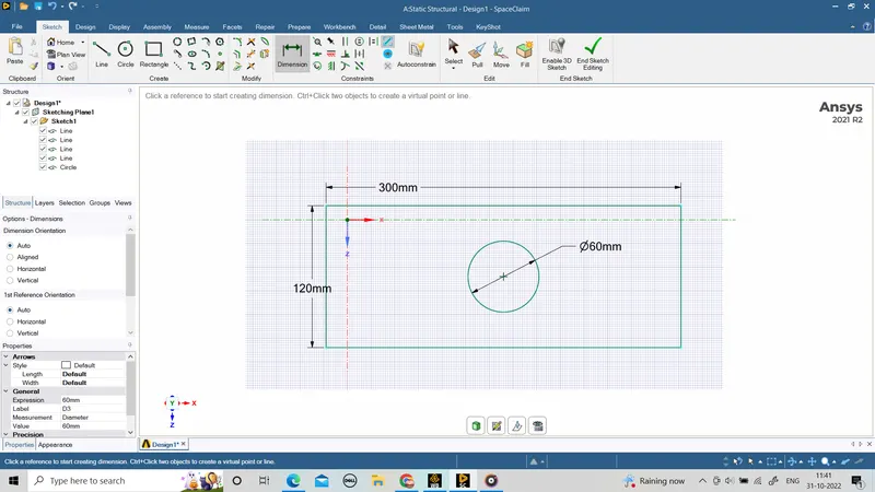
Plate dimensions:
Length=300mm
Height=120mm
Thickness=30mm
Circular Hole at the center:
Diameter=60mm
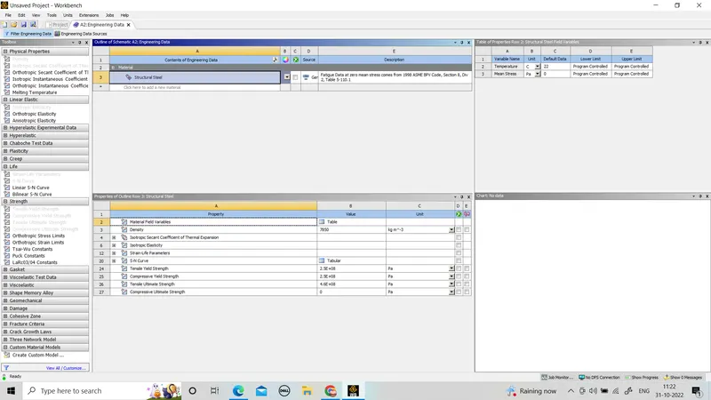
Update the Default material (Structural steel) to the System, under the Engineering data.
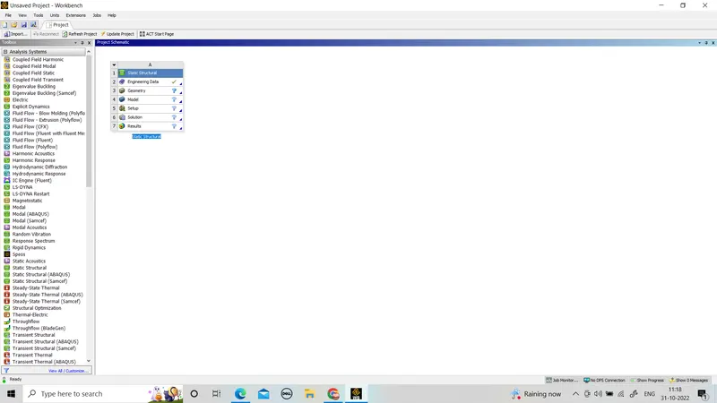
Assign the material.
Design a rectangular plate with hole by using space claim and assign the Dimension.
By using pull option assign the thickness of the plate as 30mm.
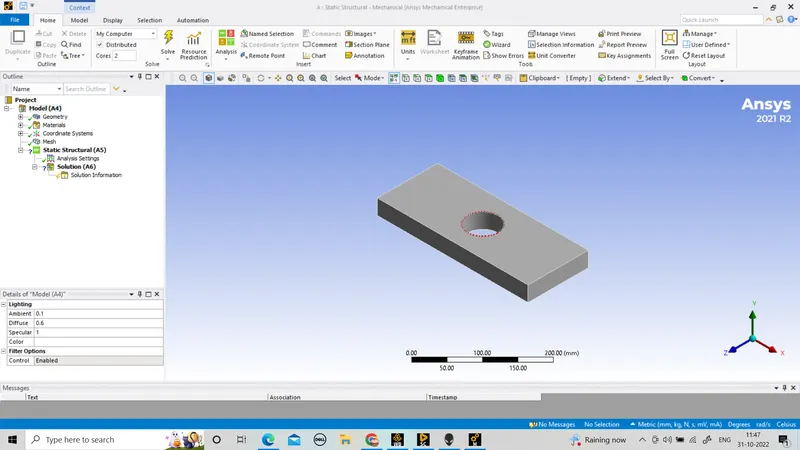
After creating the geometry move to model option.
Model option is used to assign the support and force to the component.
One end has fixed support and another end has force to apply on it.
mesh can be generated.
In mesh option use methord option.
by using methord option assign the tetraherons on it.
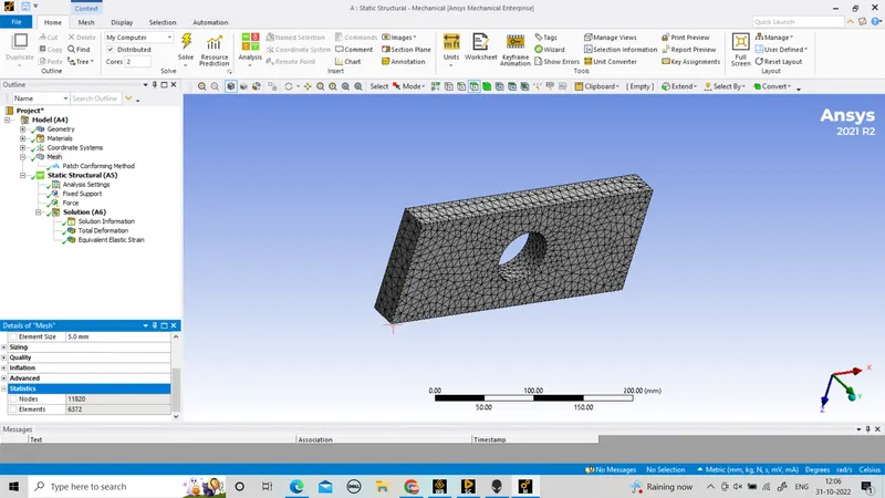
mesh can be done by the element sizing of 5mm.
After mesh can be done apply the support and force to the model.
One end has fixed support and another end has force to apply on it.
Fixed support ca nbe used to fixed the left end.
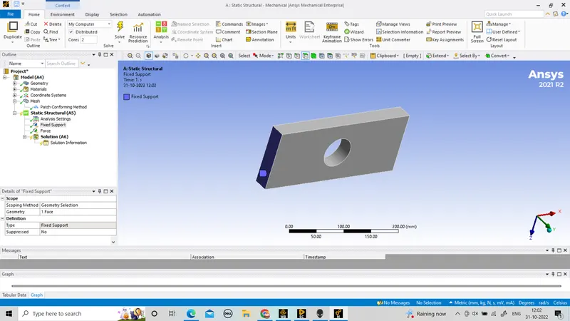
After applying the fixed support and apply force on the right side.
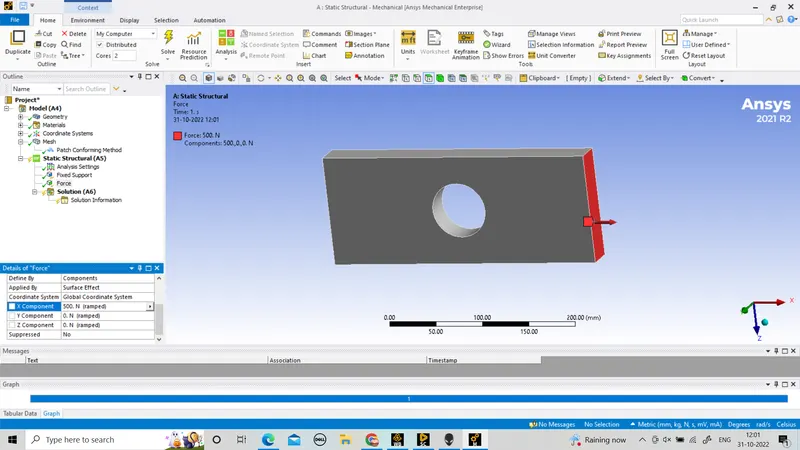
Force should be apply on X-direction by 500N.
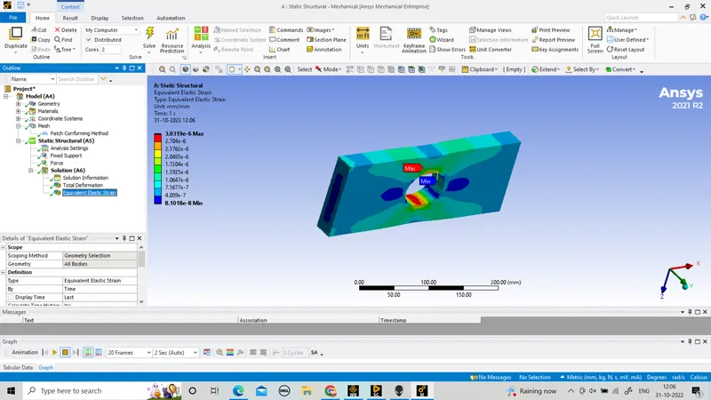
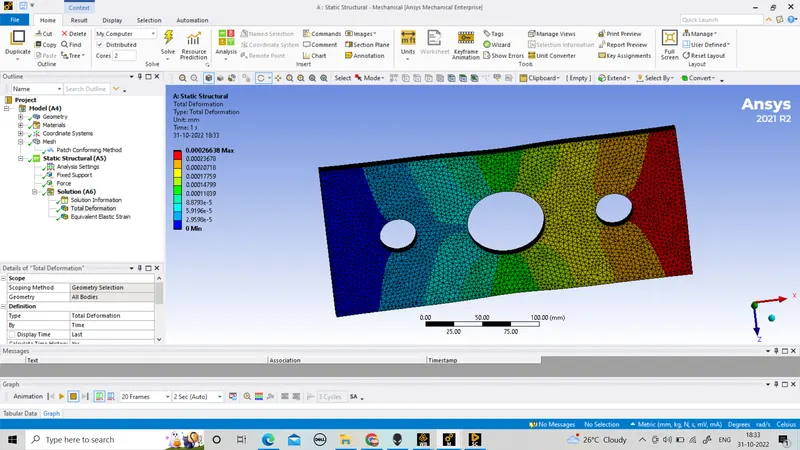
In solution option apply total deformation and von-mises stress.
solve the model.
Total deformation.
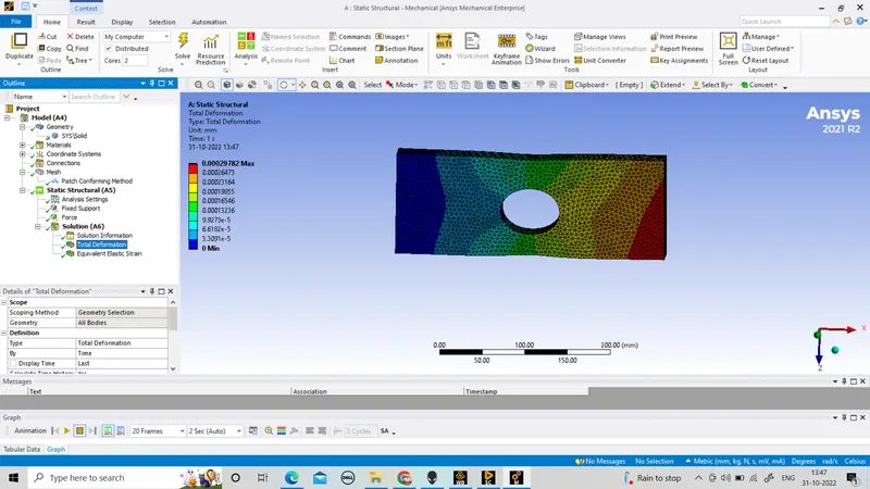
von-mises stress
CASE 2
Open the ANSYS Workbench software. Under the Analysis system select the Static structural panel.
smaller holes 90mm away from the center:
Diameter=30mm
Boundary Conditions:
Plate fixed at left face.
Load of 500N on the right face.
Update the Default material (Structural steel) to the System, under the Engineering data.
Assign the material.
Design a rectangular plate with hole by using space claim and assign the Dimension.
By using pull option assign the thickness of the plate as 30mm.
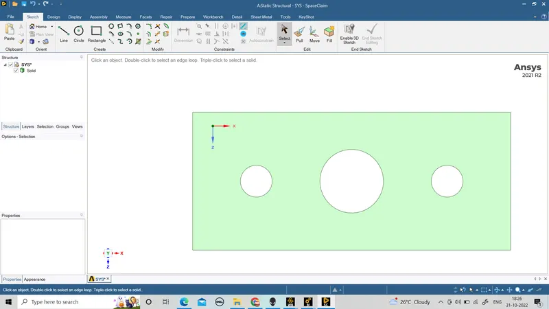
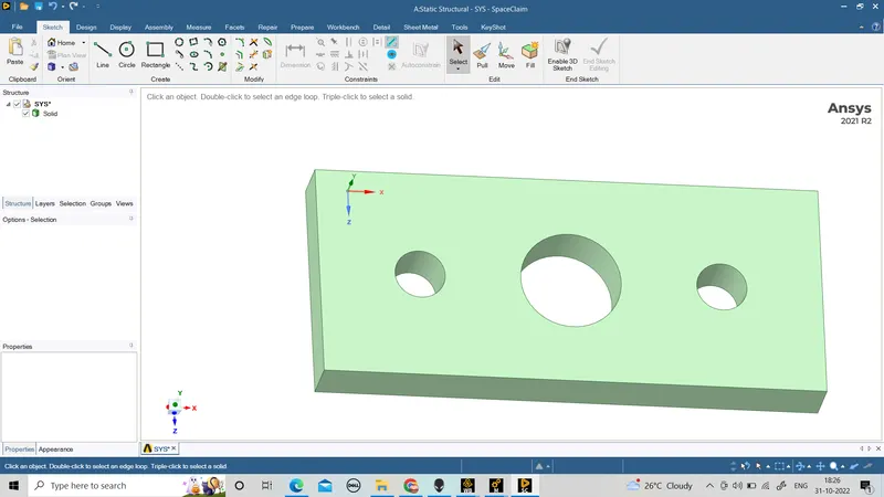
fter creating the geometry move to model option.
Model option is used to assign the support and force to the component.
One end has fixed support and another end has force to apply on it.
mesh can be generated.
In mesh option use methord option.
by using methord option assign the tetraherons on it.
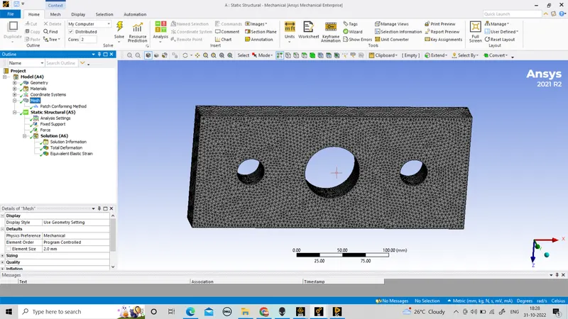
mesh can be done by the element sizing of 5mm.
After mesh can be done apply the support and force to the model.
One end has fixed support and another end has force to apply on it.
Fixed support ca nbe used to fixed the left end.
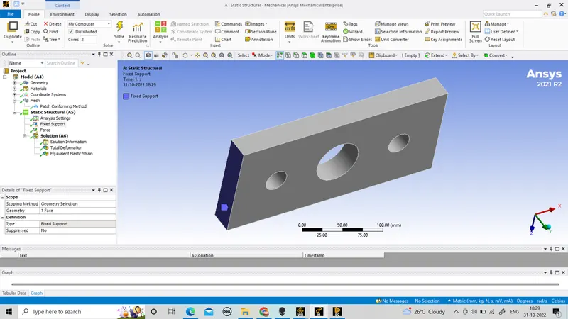
After applying the fixed support and apply force on the right side.
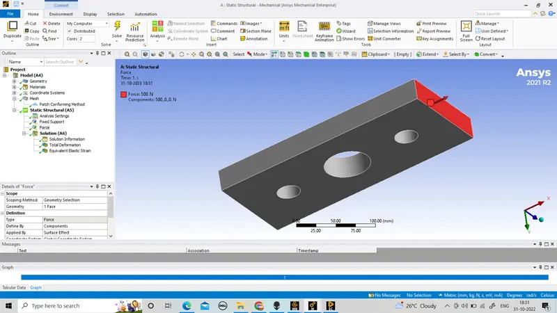
Force should be apply on X-direction by 500N.
In solution option apply total deformation and von-mises stress.
solve the model.
Total deformation.
von-mises stress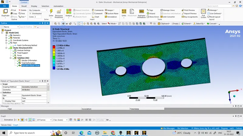
RESULT
Comparision of the deformation and maximum stress developed on a structural steel model of two cases.
|
CASES |
Deformation (mm) |
maximum stress |
|
Case-1 |
0.00023782 |
3.1886e-6 |
|
6e-6Case-2 |
0.00026638 |
2.5182e-6 |