Week 1 Stress Concentration on a Plate with hole
Objective
To perfrom a static analysis for a plate with a hole with two cases using Ansys workbench and to compare their results for maximum stress and deformation.
Procedure
Case 1
- Ansys workbench was opened and a static structural module was dragged onto the project schematic window.
- The material for the model can be assigned from the engineering data. Here the default structural steel material was loaded for the simulation.
- The required geometry of a plate with a hole with the required dimension can be modeled either from the design modeler or the space claim. While assigning the dimension check whether the unit system is assigned correctly or not
- After making the sketch it's then extruded to get a thickness of 30mm.
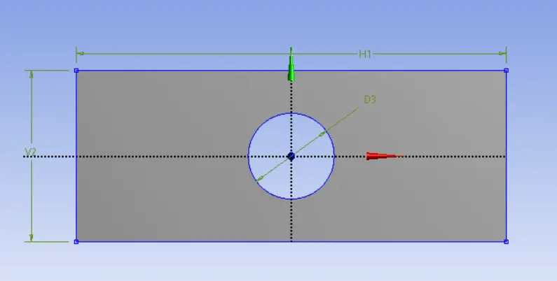
- Now the model option from the structural module was selected to do the meshing and case set-up for the model.
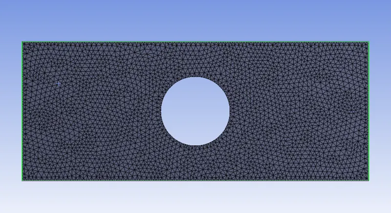
- The model was given an element size of 2mm. Here also the units should be checked and can be changed if needed.
- Here the model was meshed using tetra elements and it can be selected using right-click mesh>Insert>method>select geometry>method>change to the tetrahedron.
- The generate or update option can be now used to generate the mesh.
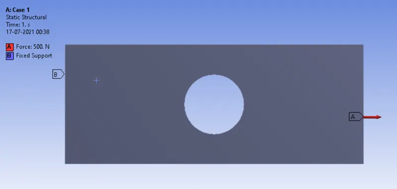
- Boundary conditions were defined by fixing one face and providing a force of 500N to the other face. This can be done by right-clicking static structural>insert>fixed support | force.
- The required output such as equivalent stress, total deformation can be requested by right-clicking solutions>insert>(select as per the need).
- Now click solve to start the simulation.
Case 2
- For case 2 the geometry was modified by adding holes on either side of the central hole. So a new static structural model was again dragged onto the project schematic window.
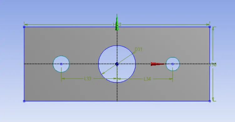
- The same procedure was followed to do the simulation as that did with the above model.
Results
- The structural simulation for plate with hole has been simulated for both the cases and the results got from the simulation are discussed below.
Effective stress
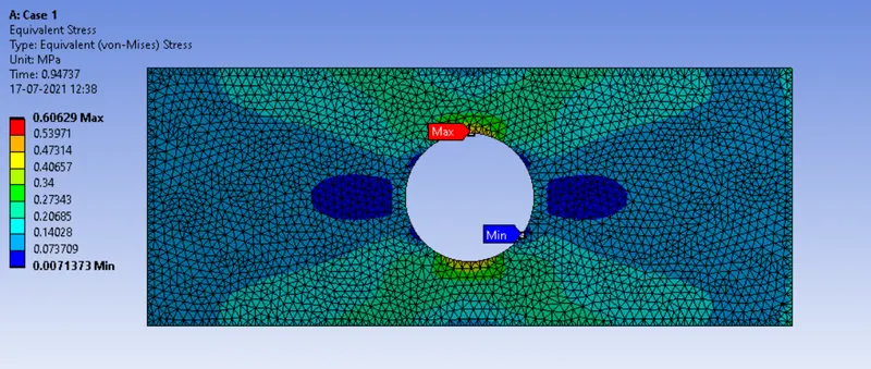
case 1:
Case 2:
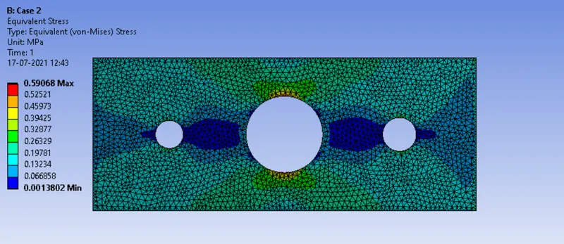
- From the plot it can be observed that the maximum effective stress for the case 1 is more (0.60629MPa) when compared to case 2 (0.59068MPa). Also the maximum stresses are found to be at the hole region. This is because of the stress concentration happens when there are irregularities in the geometry or material of a structural component that cause an interruption to the flow of stress. This arises from such details as holes, grooves, notches and fillets. Stress concentrations may also occur from accidental damage such as nicks and scratches. The stress concentration can be reduced by including gradual transition in the design, using relief notches, avoiding sharp corners etc.
- When additional holes were used in the case 2 we can observe that stress concentration was found to be less than the case 1. It is because the extra holes retard the crack growth and had a positive effect in reducing the stress concentration.
Total deformation
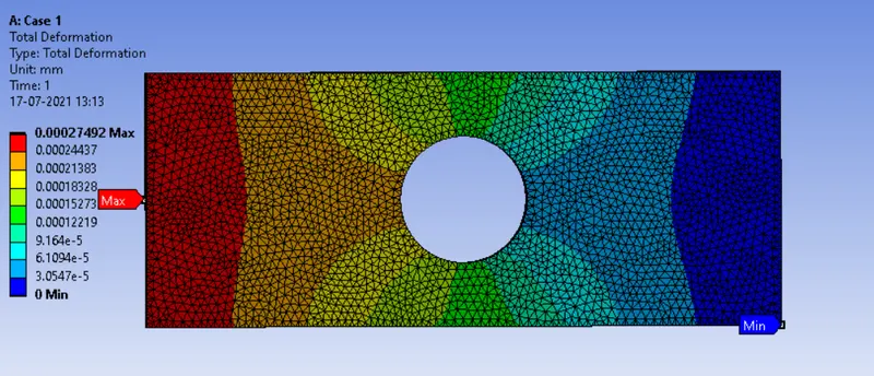
Case 1:
Case 2:
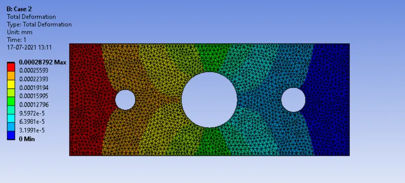
- The above plot shows the total deformation and there is only a little difference in the values between canse 1 and case 2. The maximum deformation for case 1 is found to be 0.00027492mm and for case 2 it is 0.00028792. The difference in the elongation for the case 2 is slightly more because of the extra feature provided on to the plate.
Design from analysis point of view
- Design of case 2 with the additional holes can be selected from analysis point of view since the model was optimised and was able to reduce the stress from 0.60629MPa to 0.59068MPa which will retard the crack growth and will have a positive effect in reducing the stress concentration there by making it durable.
Design from manufaturing point of view
- Design with single hole from the case 1 can be chosen as per the manufacturing point of view since while manufacturing the product it may require more time to drill those extra hole that in the case of case 2. Also there is not that big deviation in the results that we got to effect the product life, It would be better to go with case 1 inorder to save time and the cost of production.