Week 1 Spur Gear Challenge
Aim: To perform a static structural analysis on the Spur Gear in Ansys Workbench.
Objective: To compare the results of the three cases mentioned and conclude that which material is best based on the results.
Case 1: Using Cast Iron(ductile) as a material, carry out a static structural analysis to find out Equivalent stress, Total deformation and Stress intensity(Learn about what stress intensity is). Find location for possible fracture.
Case 2: Using Cast Steel as material, perform the same analysis for the results as in Case 1.
Case 3: Using Cast Bronze as material, perform the same analysis for the results as in Case 1.
Introduction:
Spur gears are a cylindrical shaped toothed component used in industrial equipment to transfer mechanical motion as well as control speed, power, and torque. These simple gears are cost-effective, durable, reliable and provide a positive, constant speed drive to facilitate daily industrial operations. Spur gears are one of the most popular types of precision cylindrical gears. These gears feature a simple design of straight, parallel teeth positioned around the circumference of a cylinder body with a central bore that fits over a shaft. In many variants, the gear is machined with a hub which thickens the gear body around the bore without changing the gear face. The central bore can also be broached as to allow the spur gear to fit onto a spline or keyed shaft. Spur gears are used in mechanical applications to increase or decrease the speed of a device or multiply torque by transmitting motion and power from one shaft to another through a series of mated gears.
The stress intensity factor (K) is used in the field of fracture mechanics. It predicts stress intensity near the tip of a crack caused by a remote load or residual stresses. The magnitude of K depends on:
- Sample geometry
- Size and location of the crack
- Magnitude of load
- Distribution of load
Procedure:
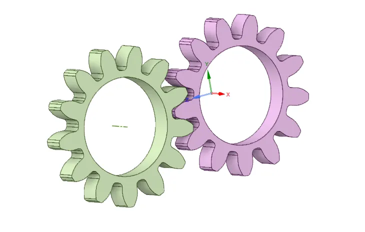
- After opening Ansys Workbench, use static structural as the mode of analysis for simulation.
- Import the geometry given and check the geometry in the Ansys Spaceclaim for any abnormalities.
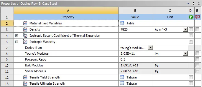
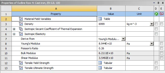
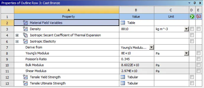
- Assign Material as Cast Bronze for the first simulation:
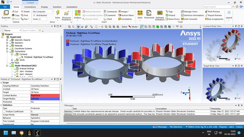
- Create frictional contact points between the gears:
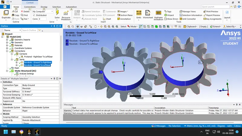
- Create revolute ground to body joints.
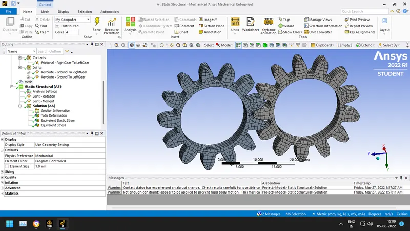
- Mesh the gears with an element size of 2 mm.
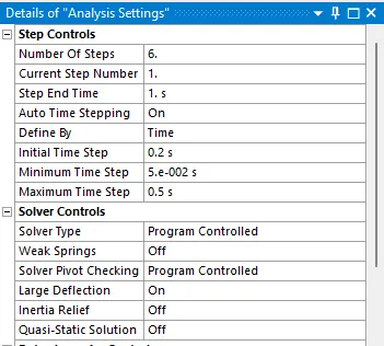
- Now in analysis settings keep no. of steps as 6 and turn on large deflection as shown below:
. 
Add Joint rotations for 180 degree and moment of 10000 for the gears as shown below in z direction:
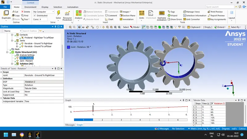
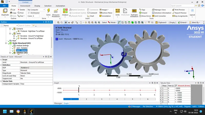
- Insert Equivalent stress, Total deformation and Stress intensity in the solution.
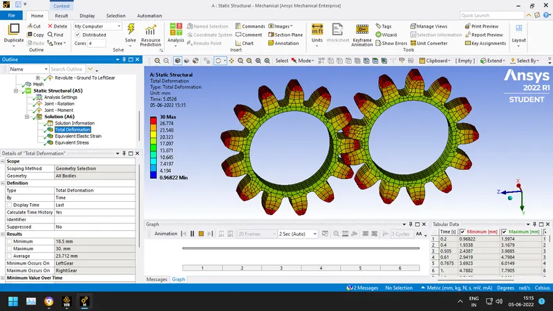
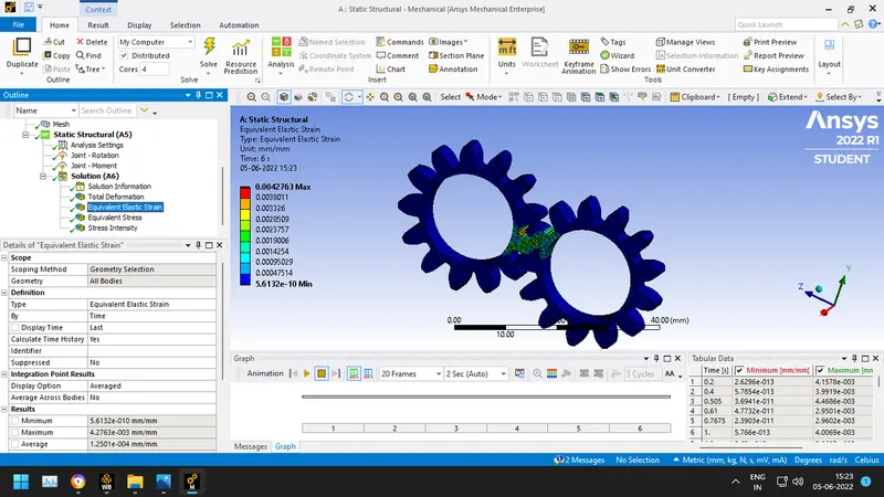
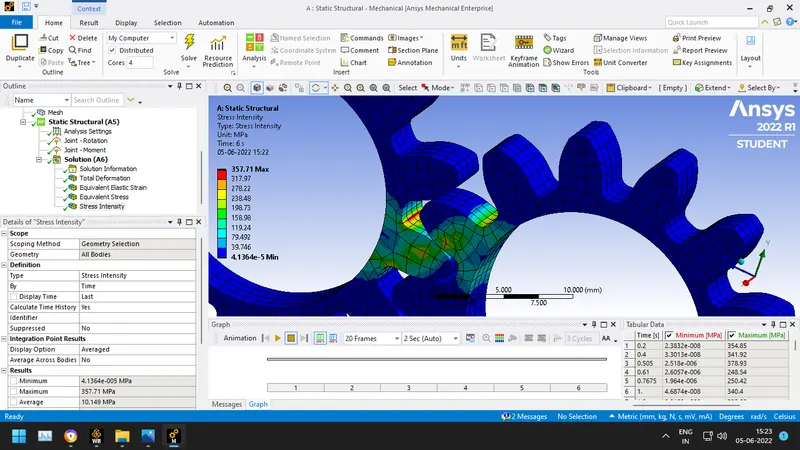
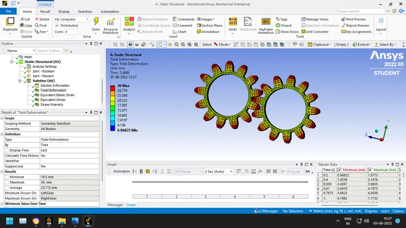
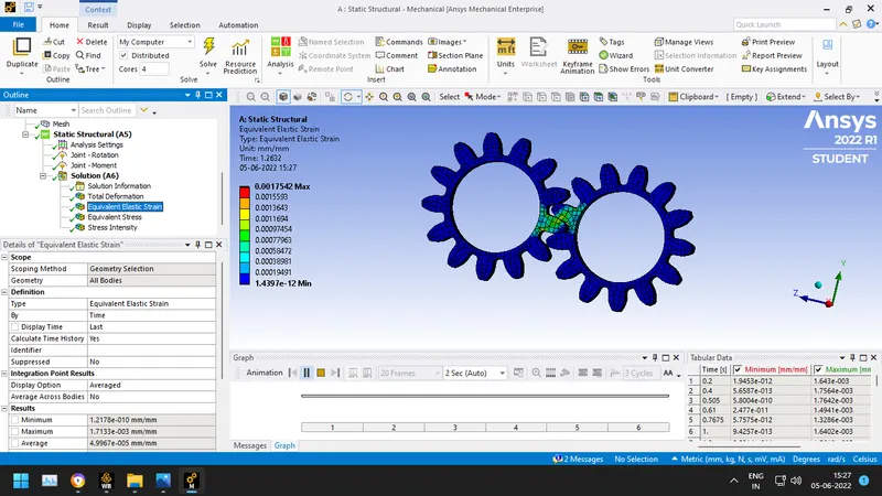
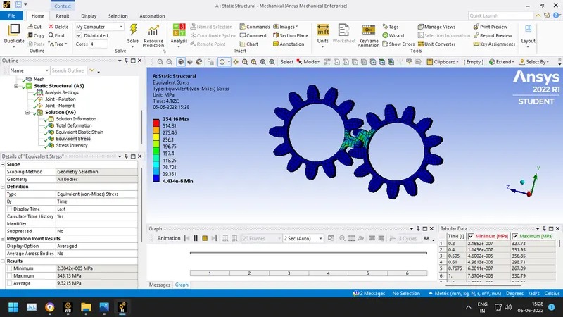
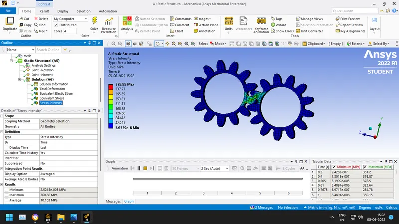
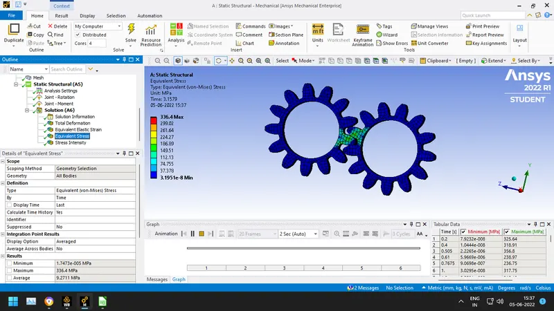
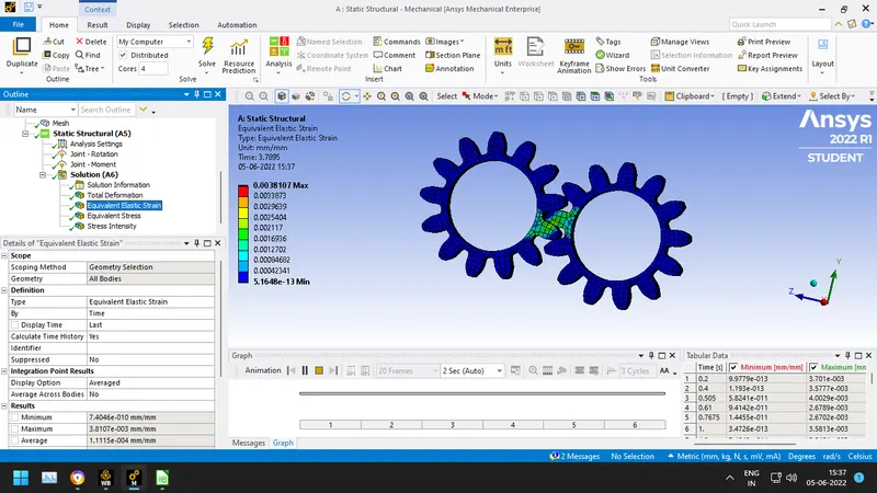
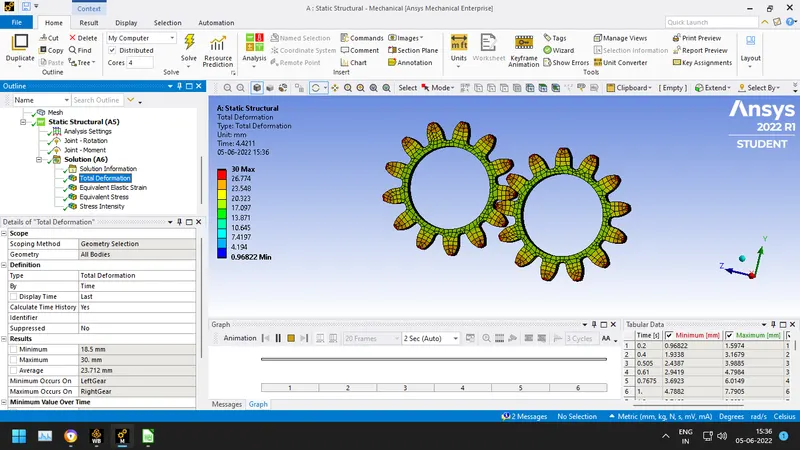
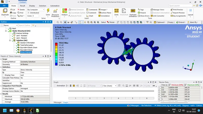
- Following Solutions have been obtained after running the simulation:
Case 1) For cast bronze.
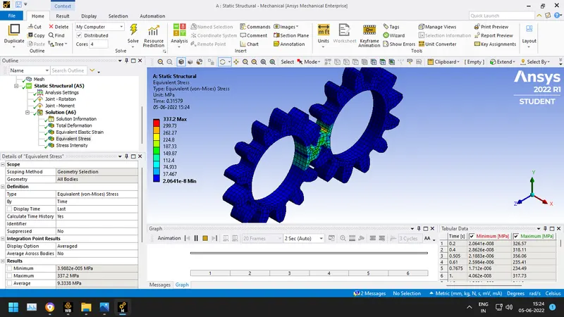
Case 2) For cast steel
Case 3) For cast iron
Conclusion:

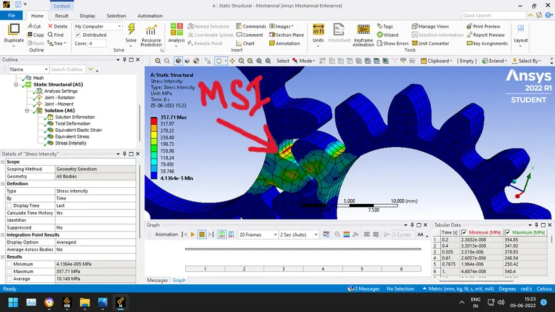
From the above results, we can see that the cast steel generates the highest stress and highest stress intensity among the three. The lowest stress and stress intensity is generated in cast iron. Hence, if a material is to be selected among the three cast iron is the best.
The deformation is seen to be the same in all the three cases. The maximum strain is seen in cast bronze.
The stress intensity or the location of fracture where the gear may fail at the root of the tooth as shown below: